 |
Fred's Fusor
Reactor |
|
Contents
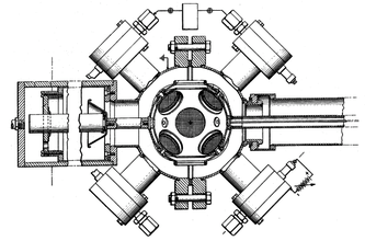
of this page Introduction The reactor is the vacuum chamber with its attached components, such as the vacuum inlets and outlets (amongst which the Deuterium precision regulable valve), and the HV feedthrough and its connected grid. Ideally the vacuum chamber is a sphere with dimensions of about 160 to 200 mm diameter and consisting of two half-spheres, which are connected together by means of either conflat or ISO DN vacuum flanges. For low budgt purposes it is quite possible to weld two stainless steel salad bowls together, which have appropriate openings for welding half nipples into them. An example of a stainless steel half nipple (size KF40) is shown in image 1, standing on the KF40 connector side with the welding connection at the top. 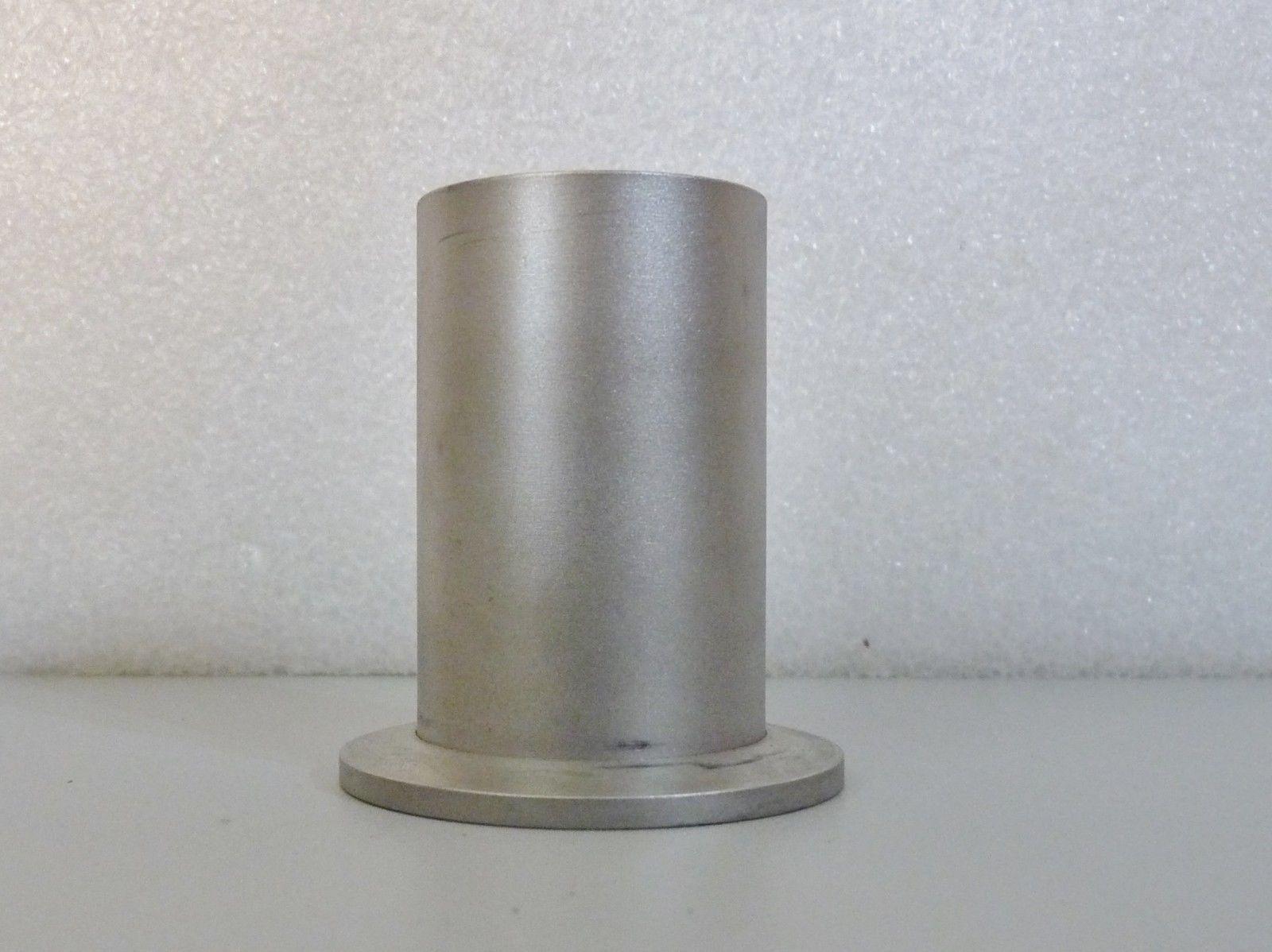 Image 1: Welding half
nipple KF40
When the ideal (half) sphere(s) is/are not available than the vacuum chamber can be made of any suitable vacuum connection cross or a Pyrex glass vacuum reaction jar. When a glass jar is used, a second large gitter is required alongside the walls of the jar as the ground HV connection. With a fully steel housing the housing usually acts as the ground potential. Furthermore, with a glass jar care should be exercised by applying lead shielding to the jar because at HV potentials > 15 kV X-rays will be produced, which escape into all directions through the glass. The advantage of a steel vacuum chamber is that it will shield X-rays up to a certain level. An example of a suitable vacuum cross is shown in image 2:  Image 2: Vacuum cross
suitable as Fusor vacuum chamber
The vacuum cross in image 2 has right and left DN200 flanges (200 mm dia) and top and bottom DN160 flanges. The two small connectors at the bottom and the top neck of the flanges are KF 16 connectors and the connector in the center of the cross is a conflat 2.5" connector. This very fine piece of stainless steel has a weight of 42 kg. This vacuum cross unfortunately could not be obtained because of a too low bid in an auction and therefore another solution will have to be found. In the sections below we will describe our efforts to construct a suitable vacuum chamber, for which we had to change our plans more than once. Changing the plans is caused by the fact that we constantly search dumpstores and the internet to find suitable, cheap equipment. The initial plan was to find components for constructing a spherical Fusor with a diameter of 160 to 200 mm but at the same time we were looking for suitably large crosses or T-pieces, which are equally qualified for constructing a Fusor. Since the beginning of the project the concept of the vacuum chamber changed as follows:
 Vacuum Chamber For the construction of the first model of the Fusor (Abel_1) it was the intention to use two stainless steel salad bowl half spheres (image 3): 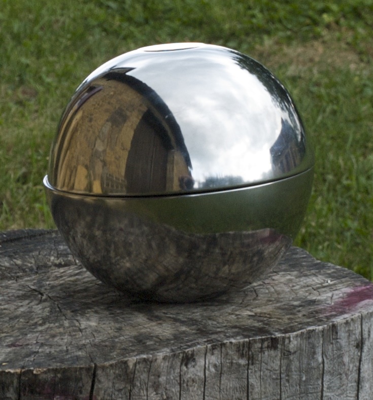 Image 3: Stainless
Steel Half Spheres, diam 200 mm (© FRS 2014)
The two stainless steel (ss) half spheres have a diameter of 200 mm and a wall thickness of 1.5 mm. Prior to welding the half spheres onto a flange, the folded rim will have to be cut off from the edge rim. Because my welding skils for ss are below standard and because a rather high investment would have to be made in welding equipment such as a high amperage TIG welder, the idea to use salad bowls was quickly abandoned. As it was not the intention to build nuclear fusion reactors in large series it was considered a better idea to invest the money for a welder in higher quality ss spheres, a set of high vacuum flanges and a centering vacuum ring. Construction of the reactor by means of welding could than be outsourced to a professional welder, or, if this appeared to be too expensive, by brazing the components together with silver solder. Brazing is a technique that can be done in my workshop as a propane/oxygen brazing torch is part of the toolset. However, for brazing it would be prefarable to buy the half spheres in a thickness higher than the 1.5 mm of the salad bowls. The advantage of a thicker wall thickness is that a recessed opening can be milled for fitting a half nipple by means of brazing, e.g. for fitting a KF 40 half nipple we firstly mill a recessement of 45 mm diameter one mm deep (or less) into the metal and then a final diameter of 40 mm through the metal. The recessed opening is easier to work with when centering the half nipple over the opening prior to brazing. Moreover, on the spherical surface of the metal by milling we will obtain a fully flat surface for placing the half nipple onto and this is required for the brazing process, i.e. the space between two objects to be brazed should be rather tight and even in order to obtain a capillary suction force to spread the silver solder between the objects. The thinner the joining solder layer the better and stronger the joint. For the milling we will use HSS milling drills of the appropriate sizes, which can be obtained for diameters between 15 and 80 mm, climbing with 2 or 5 mm steps (image 4).  Image 4: Milling Drill (source: supplier) It was decided to postpone searching for half spheres until flanges and an appropriate centering ring was found. Almost simultaneously after taking this decision a cheap 200 mm centering ring was found in Germany as well as two reasonably priced Varian O.D. 10" high vacuum flanges in the U.S.A. These three items were ordered first to find out if the centering ring could be fitted into the flanges. Then, a correct size of ss half spheres had to be found. Spherical Vacuum Chamber Project Components Centering Ring The centering ring is a size ISO 200mm DN Inficon model BP21320-T, made of aluminium with a Viton O-ring (image 5). Image 5: 200 mm centering ring (source: supplier) The centering ring consists of three parts, an inner rim, an outer rim and an O-ring. Its dimensions (image 6) are conform ISO-norm: OD 213 mm (D1), ID 210 mm (D2), an inner rim height of 8 mm (T) and an outer rim height of 3.9 mm (E). The overall diameter is 238 mm. The Viton O-ring has an inner diameter of 205 mm and a diameter of 5 mm. From these dimensions we can see that the O-ring is slighly stretched when it is fixed onto the inner rim. Also, both inner and outer rim are not endless, but have straight ends. This is an important factor with respect to the use of our flanges, described below, which are not ISO standard vacuum flanges! 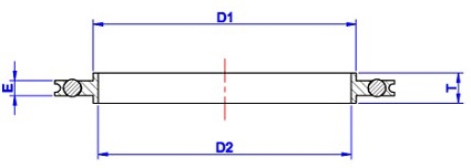 Image 6: Centering Ring (© supplier) Flanges The two stainless steel AISI 316 high vacuum flanges are made by Varian, ID no. 02277004 / 45, with an outer diameter of 10 inches (254 mm), a smaller inner diameter of 8.125 inches (206.4 mm) and a larger inner diameter of 8.75 inches (222.3 mm). the flange height is 0.965" (24.5 mm); the inner rim has a height of 0.3" (7.5 mm). The flanges have each 24 holes with a diameter of 8.4 mm for bolting the flanges together. (Images 7 and 8a):  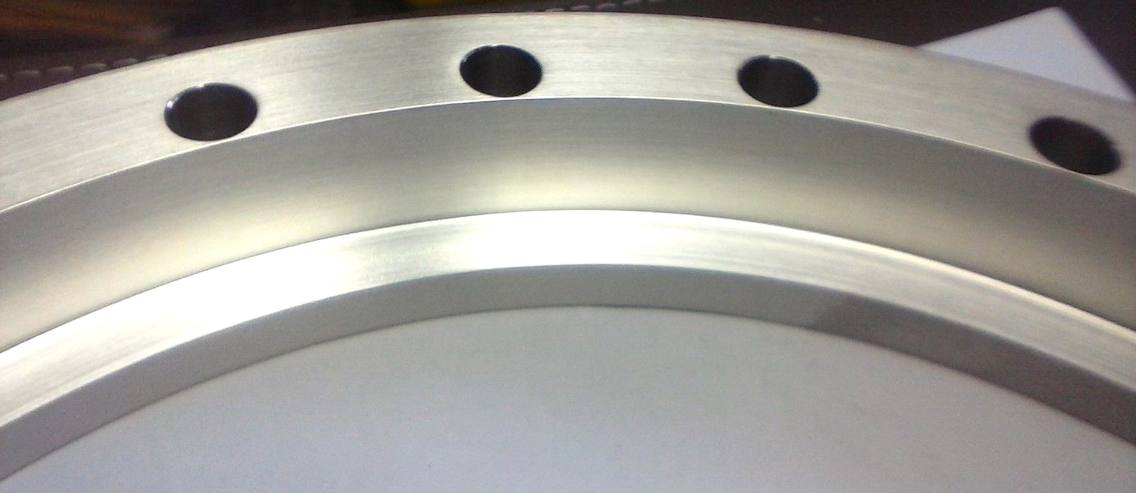 Image 7 and 8a: Varian vacuum flange and rim detail (source: supplier) The dimensions of the flange are not compatible to any known high vacuum flange and therefore it remains the question if they can be used for our Fusor. Most probably these "flanges" are fixation rings which are placed over a smaller size pipe flange. As mentioned in the previous centering ring paragraph, we have a discrepancy between the dimensions of the flanges and the centering ring. The inner diameter of the centering ring of 210 mm needs to fit into the inner diameter of both flanges, which is 206.4 mm. To make the centering ring fit into the flanges we will have to shorten the inner- and outer rim of the centering ring. A rough calculation (2 pi times r) produces a circumference of 659.7 mm for the inner rim of the centering rim and a circumference of 648.4 mm for the inner diameter of a flange. When we shorten the inner rim of the centering rim with 659.7 - 647.2 mm = 12.5 mm we should obtain a rather tight fit in the flange. After shortening, the inner rim will have a diameter of 206 mm, just enough to fit the O-ring, with a diameter of 205 mm, with a very, very slight tension onto the inner rim. Consequently we also will have to shorten the outer ring of the centering rim. As we have shortened the diameter of the centering ring with 210 - 206 = 4 mm, the outer rim diameter is also to be shortened with 4 mm and becomes 238 - 4 = 234 mm, i.e. we will have to shorten the old circumference of 747.7 mm to a new circumference of 735.1 mm, or a shortening with 12.6 mm. Now we only still need to check that the shortened centering ring does not cover the fixation holes in the flanges. Unfortunately this is the case: the outer rim of the centering ring partly covers the fixation holes and we need to find a solution for that. The outer rim does not play a part in maintaining vacuum inside the vacuum chamber. Its only apparent mechanical function is to prevent the O-ring from being squeezed to the outside when the flanges are pressed together by the bolts and thus creating an insufficent vacuum tightness. Therefore we can replace the rather broad outer rim by a thin strip of stainless steel, welded into a ring, and just laying against the fixation bolts (to give a fixing support and to prevent the O-ring moving to the outside). The height of the ss strip is 3.9 mm (equal to the outer rim) and its thickness needs to be determined live in the work, i.e. with the altered centering ring placed into the flange. The length of the strip prior to welding into a circle is 665 mm, which length is calculated with the measured diameter between two opposite holes. In case it appears to be too difficult to find or make such a stainless steel strip, we can use aluminium instead, which is less difficult to cut. However, as we are not able to weld aluminium (for which an AC TIG welder is required) we should connect the two ends of the strip in the space between two bolts on the flange as this provides ample space for a tightening construction. The easiest way to do this is by taking a slightly longer length of aluminium strip (add 2 times 10 mm of length) and by bending the excess length in 90 degree angles pointing away from the O-ring. By cutting slits in the angled parts we can turn the strip into a ring by closing it with a short M2 screw and nut or a twisted wire. All this is quite a lot of work to turn a standard centering into a one-off made-to-measure one! Another remaining problem now is to fit half spheres with a diameter of 200 mm exactly into flanges with an ID of 206.4 mm, leaving a distance of 3.2 mm to be bridged by means of welding around half sphere and flange. Fortunately, for TIG welding filling rod exists in a 316 type stainless steel with a diameter of 3.2 mm and a length of 1000 mm. It appeared to me that one such wire (cut off to a length of 647 ± 0.1 mm) can be pressed into the space between the half sphere and the flange, whereafter two welding joints will attach the parts together, vacuum tight. Half Spheres Two half spheres made of stainless steel AISI 304 with an outer diameter of 200 mm, a height of 100 mm and a wall thickness of 2 mm are used for constructing the vacuum chamber. (image 9):  Image 9: Stainless Steel Half Sphere 200 mm (source: supplier) Before we proceed with welding the half spheres into the flanges we will need to drill the appropriate openings for the half nipples into the half spheres. See the half nipple paragraph below. As described above we will need to fit the half spheres into the flanges by pressing a filling rod between flange and half sphere. For fitting the half spheres into the flanges with help of the filling rod it is required firstly to make a mounting jig and a support. The mounting jig serves to obtain a neat and symmetrical fit of the half sphere into the flange, some 5 mm up from the edge of the inner rim.  Image 8b: Varian Flange Rim Detail (source: supplier) In image 8b the distance A to B on the inner rim is 7.5 mm; the line d to e has been drawn at a height of 5 mm from point A. This is the deepest point until which the half sphere can be welded onto the flange because the rim space from point A to the line d to e needs to be reserved to accomodate the inner rim of the centering rim. With other words the flange side below point A is the surface that connects to a similar surface of the other flange. In order to obtain a perfect fit of the half sphere and leaving 5 mm deep of the flange unobstructed we need to construct a rather precise jig of 5 mm height and a diameter of 206.4 mm. This can be made of wood, e.g. 5 mm thick multiplex. The diameter of the jig should be precise in order to obtain a tight fit. Pre-drill a small hole exactly in the center of the jig. We place the jig onto a flat surface and press the flange (point A down) over the jig. Then place the half sphere inside the flange onto the jig, more or less concentrically. Take the cut to length 3.2 mm diameter welding rod and push it firmly into the gap between half sphere and flange. Use a soft (wooden, plastic) 3 mm thick wedged driver and a light hammer. When the welding rod is flat onto the jig surface the half sphere should be fitted with a compressed fit into the flange and is will be impossible to separate the two. When a tight fit of the half sphere and the flange cannot be obtained than weld flange, rod and flange together on four small spots at 90 degrees. Now, turn the flange and half sphere assembly upside down and place it onto a pre-made support of wood, dimensions inside 220 mm square and 200 mm high. Screw a wood screw into the pre-drilled hole in the center of the jig and pull the jig out of the flange. When the fit is too tight use for removal of the jig a sliding hammer as used for car coachwork repairs. Finally, weld the flange, rod and half sphere from the inside of the flange together (first four spots at 90 degrees, than short tracks at alternating sides). We can do the welding ourselves when we have access to a DC TIG welding station but the large amount of steel from the flange may require a more professional type of welding machine than the standard hobby machines that are popular nowadays. This has to do with the fact that a thicker piece of steel requires more Amps for welding than the maximally available 200A from the popular machines. An output of 200 A corresponds with a power inpout rating of about 4 kVA and that is the maximum that is available in a European) single phase 16 A fused 230 V "common household" power supply line! After all welding has been done and assuming that a good professional result has been obtained, it will be necessary to grind the welding seams to a reasonably flat surface (without breaking the vacuum tightness!) and to start a series of finishing treatments, such as pickling and/or etching possibly followed by (electro)polishing. More detailed information about these processes can be found on the Engineering Works page. Note: Grinding and sandpaper polishing is by some fusioneers preferred over the electrochemical processes because it is said that the residues from the electrochemical processes are more difficult to wash off and may cause problems in baking out the vacuum chamber! Bolts For bolting the flanged half spheres together we will need 24 stainless steel bolts M8 x 60 mm with M8 nuts. Welding Half Nipples Construction T-piece Vacuum Chamber Project The T-piece vacuum chamber project is a rather simple construction consisting of easily available parts. This makes it an ideal project for an intermediate Fusor project intended to gain some experience before a larger spherical reactor will be constructed. The schematic layout of the cylindrical reactor is shown in image 10:  Image 10: Schematic Layout Cylindrical Reactor (© FRS 2017) Apart from the components as shown in the image, additional components will be added to complete the reactor, such as the pneumatic controllers, a manual switch panel, the Deuterium Gas Supply unit, a High Voltage power supply, a 12V DC power supply for the colling fans and a 24V DC power supply for the pneumatic valve controls. Components The reactor is constructed for operation with our turbo pump with ISO-DN 63 flanges and the butterfly valve also with ISO-DN 63 flanges. The setup consists of the following parts:
The stainless steel ISO-DN 100 T-piece was obtained in an auction for € 25,72 and it has an inner diameter of 100 mm, a flange outer diameter of 130 mm and a heigth of 215 mm. The circumference is 343 mm, which gives us an outer diameter of 109.2 mm or a wall thickness of 4.6 mm. (image 11).  Image 11: ISO-DN 100 T-Piece (source: supplier) The T-piece shall serve as the reaction chamber. It will have to be modifiied by welding a KF 40 connector into it for the roughing vacuumline, located opposite the ISO 100 side opening, and at 90 degrees of the opening by welding a KF50 connector into it for a view port. The side opening will be closed with an ISO-DN 100 flange with a High Voltage feedtrough connected to the cathode grid. The top opening will be closed with an ISO-DN 100 flange with a Deuterium Gas Injector mounted onto it. The bottom opening will be connected to a ISO-DN 100 to ISO-DN 63 reducer. Between all closures a centering ring with Viton O-ring will be placed. All closures will be fixed with ISO-K double clamps. ISO-DN 100 to ISO-DN 63 Reducer The stainless steel ISO-DN 100 to ISO-DN 63 reducer was obtained in an auction for € 54,84 (image 12). 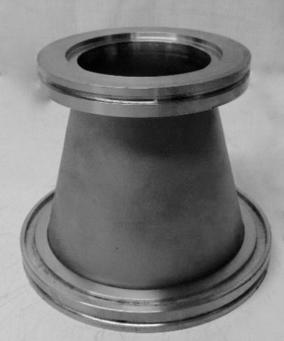 Image 12: ISO-DN 100 to ISO-DN 63 Reducer (Source: supplier) The large flange of the reducer connects to the T-piece and the smaller flange connects to the Butterfly Valve. ISO-DN 100 Flange The top and the side openings of the T-piece will be closed with ISO-DN 100 flanges (image 13), which will be machined with openings and half nipples welded into them for the HV feedthrough and the viewport. Extra half nipples may be placed for connecting to vacuum pressure sensors.  Image 13: DN-100 ISO-F flange (Source: supplier) This particular type of ISO-F flange needs to be fastened with ISO-F clamps (see below). Centering Rings For making a vacuum tight connection between the components we will use centering rings with Viton O-ring in the sizes ISO-DN 63 and ISO DN-100 (images 14 and 15). 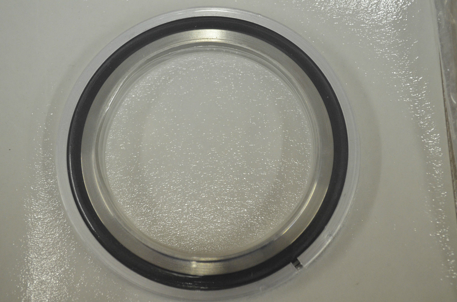 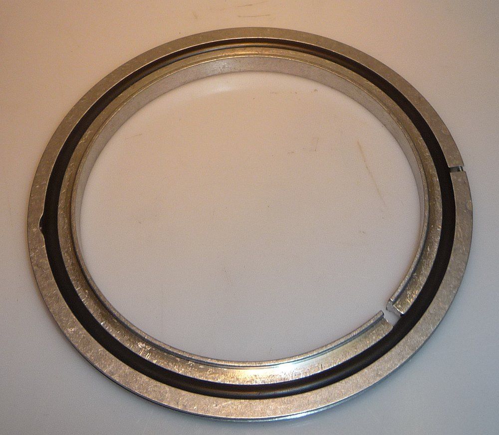 Images 14 and 15: ISO-DN 63 (left) and ISO-DN-100 (right) Centering Rings (Source: Supplier) Splitter Screen An ISO-DN 100 splitter screen will be inserted between the T-piece and the Reducer (image 16). 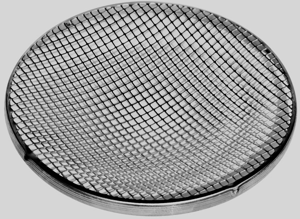 Image 16: ISO-DN 100 Splitter Screen (Source: Supplier) The function of the splitter screen usually is to prevent small parts from being sucked into the turbo pump and damaging it. In our case it has the additional fuction of dimensioning the electric field area inside the reactor, acting as a Faraday shield. Butterfly Valve The Butterfly isolating valve (image 17) has been described elsewhere on this website. It is used to isolate the vacuum chamber from the foreline circuit, which consists of the turbo pump assembly.  Image 17: Edwards Butterfly Valve (Source: Supplier) The Butterfly valve has ISO-F 63 flanges and needs to be connected with ISO-F clamps on both sides. Turbo Pump The Turbo Pump has been described elsewhere on this website (image 18).  Image 18: Agilent Varian Turbo Pump (Source: Supplier) The turbo pump has an ISO-K 63 flange and is connected to the butterfly valve. Clamps Depending on the type of flange we will use ISO-K double clamps or ISO-F single- or double clamps (images 19 and 20).  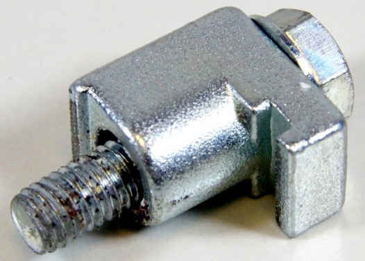 Image 19 and 20: ISO-K double clamp (left) and ISO-F single clamp (right) (Source: Supplier) Construction Despite that we have a large workspace it seemed a good idea to construct the reactor on a rolling frame that carries also the vacuum pumps, the pressurized air control components and the Deuterium gas producing components. After construction of the trolley and the frame, the reactor was assembled to find the optimal place on the frame for connecting all additional components, such as the valves (image 21a, b and c).  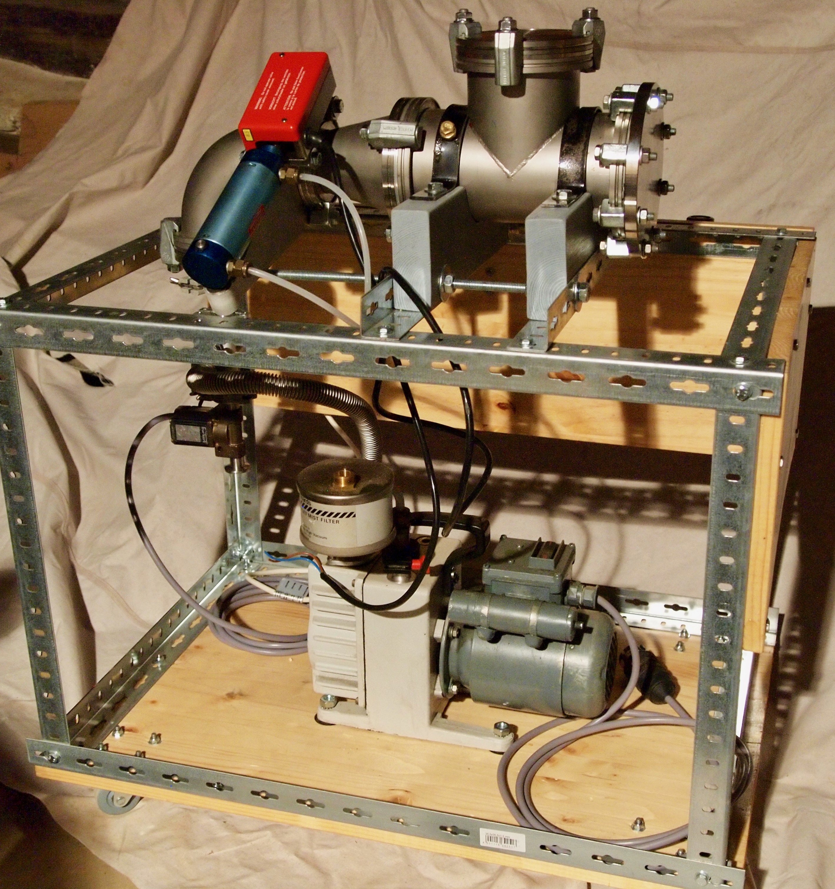 Image 21a and b: Reactor assembly (© FRS 2017) 21a) pneumatic control panel 21b backside with view on foreline vacuum pump 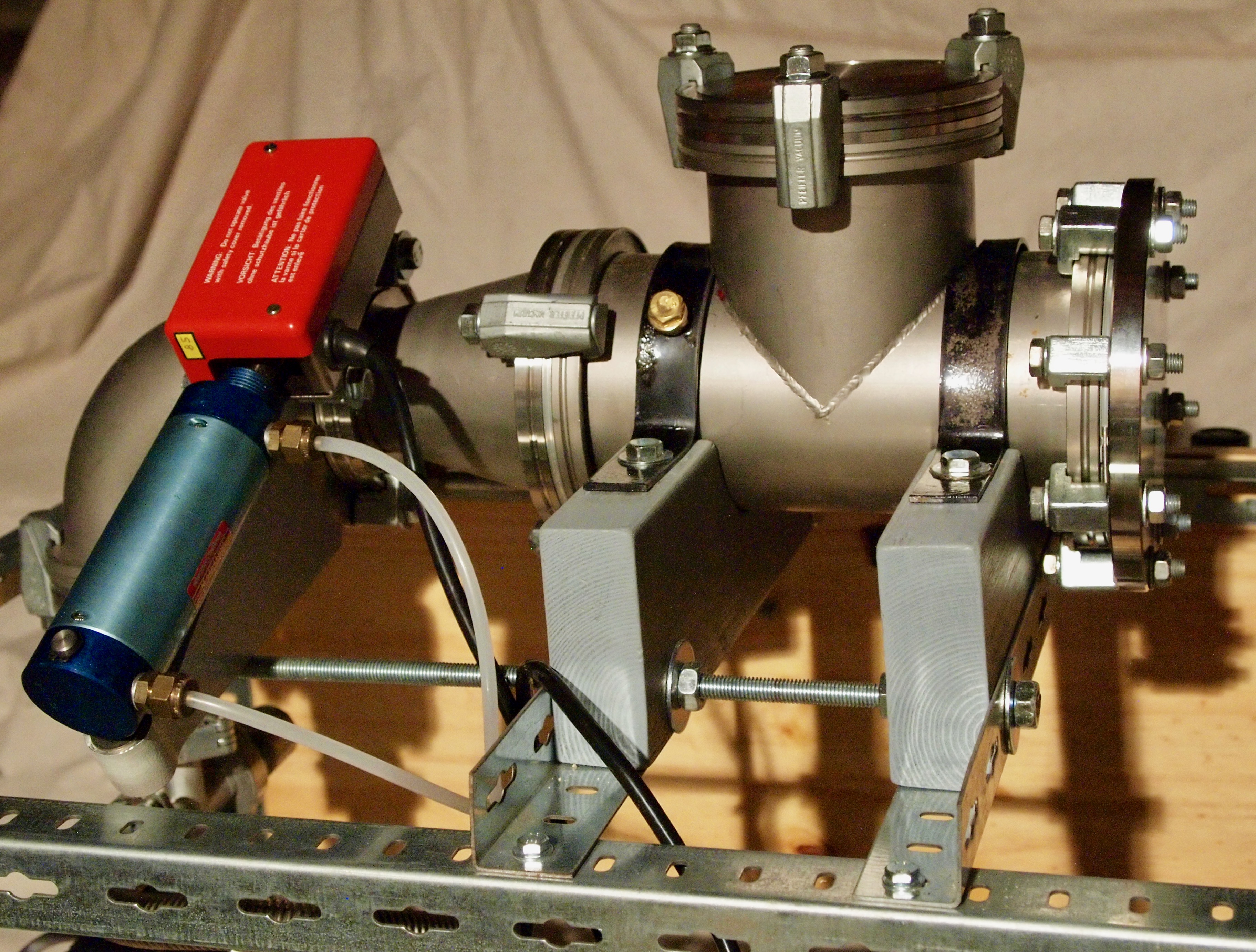 Image 21c: Close up of the reactor (© FRS 2017) Image 21c: the flange at the right side of the image is the gas entry part, the blue and red component is the main pneumatic valve and at the downwards bent outlet at the left of the image the turbo pump will be connected. The reactor assembly does not yet have the view port, the HV feedthrough, the Deuterium gas inlet and the additional welding half nipples, as the intention is first of all to assemble the reactor, the valves and the vacuum pumps in order to do a trial run to demonstrate vacuum tightness of the components present. After adding another single component we shall do another trial run in order to find out if the welding process has resulted in a vacuum tight joint and so on until all components have been fitted. This stepwise build up will assure that we can determine possible vacuum leaks in a structured way. HV Feedthrough A high voltage feedthrough is required for leading the high voltage through the wall of the vacuum chamber to the grid and keeping the vacuum intact. Even secondhand HV feedthroughs can be quite expensive and therefore it makes sense to construct one e.g. from a suitable sparkplug, which usually are good up to 30 kV. Images 22, 23 and 24 are of a typical commercial HV feedthrough, rated at 100 kV, and mounted on a Conflat 10" vacuum flange:  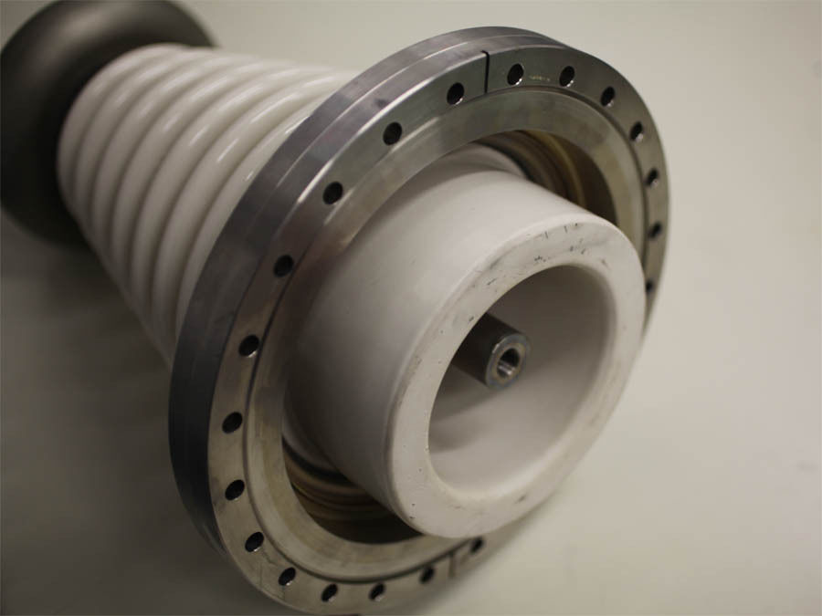  Images 22, 23 and 24:
100 kV HV feedthrough on 10" CF flange
The HV feedthrough in the images is quite oversized for use in a Fusor based on a sphere with a diameter of 160 - 200 mm. Also, it would not have fitted onto the vacuum cross in image 2. However, for a Fusor with a diameter of minimally 500 mm it could be quite useful. For our Fusor we have constructed the HV feedthrough by using a spark plug. The actual construction description can be found on the Engineering Works page of this website Grid The cathode of the Fusor is called the grid, located in the center of the vacuum chamber. The grid is connected to the HV feedthrough and is connected to a negative potential high voltage power supply. The grid is made of a good conducting, heat resistant metal and look likes a spherical Faraday cage with as main characteristic that it should contain as little cage material as possible in order to create as much as possible empty space (openings) to catch as much as possible Deuterons, which leads to the concept of grid transparancy (see the theory page, the grid paragraph). Components The grid consists of a single wire, folded and twisted into a sphere and connected to the HV feedthrough. The annealed wire, with a diameter of 0.23 mm, is made of 99.95% pure tungsten containing traces Potassium (equal or less than 0.008%), Molybdenum (equal or less than 0.005%) and Iron (equal or less than 0.002%). The material has a tensile strength of 2593 N/mm2, a resistance at 20°C of 1.34 Ω/m and a resistance at 2000°C of 16.08 Ω/m. Instead of a tungsten wire also a tungsten/rhenium wire (tungsten 74%, rhenium 26%) can be used, which metal offers better welding properties than pure tungsten. Construction  Deuterium Line A separate part of the reactor is the Deuterium Line, which has to 'inject' Deuterium gas, the fuel for the reactor, into the vacuum chamber. More about the choice for Deuterium as a fuel can be found on the theory page and more about (the preparation of) Deuterium gas can be found on the Deuterium page. For the setup of the Deuterium line see also reference 1. On this page, dealing with the reactor, the Deuterium line will be described from the point where the gas is obtained ready for use. This means that the choice to obtain Deuterium either as gas in a lecture bottle or as a liquid as Deuterium oxide, followed by electrolysis to form gas, is not discussed here but instead on the Deuterium page. Preceding the next step in the Deuterium line, the dryer, we have the following hardware in place, either a:
Dryer The dryer has the important task to dry Deuterium gas before entering the vacuum chamber. This is even the more important when Deuterium gas has been obtained by electrolysis from heavy water. The gas produced will be moist and contain heavy water vapour, which must be eliminated by the dryer. The simplest way to do this, is by applying an in-line gas filter sieve filled with Drierite (CaSO4), e.g. the Labclear DGF-250 Disposable Gas Filter Sieve Drierite (image 25) with on both sides 1/4" NPT connectors and resistant to a pressure of 125 PSI (8.6 bar):  Image 25: Labclear DGF-250
Disposable Gas Filter Sieve Drierite
The disadvantage of the CaSO4 gas dryer is that the captured moist gets lost forever, this being our precious heavy water. A cold trap instead of an absorbing filter has the advantage that the captured moist after a while can be reprocessed and re-used for electrolysis. By applying a thermoelectric cooling unit (Peltier element), the freezing element can be constructed by brazing a folded metal gas tubing with ascending slope on a block of copper, attached to the cold side of the Peltier element. From experience it is known that the cold side can reach a temperature of minus 30°C. By placing the (folded) gas line vertical and with a gas flow from the bottom to the top, the moisture will freeze out of the gas and adhere to the walls of the gas tubing. After operating the Fusor and switching off all appliances the moisture will thaw and run as liquid down into a lower part, the liquid collecting reservoir, which can be drained by closing the cold trap isolating valves to isolate the cold trap from the circuit, then opening a drain valve (some Deuterium gas in the trap will get lost). The drained fluid can be re-used in the electrolyser. See image 26 for the schematic cold trap layout. 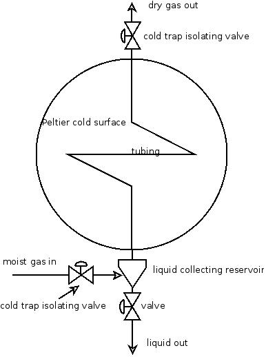 Image 26: Cold Trap
(©
FRS 2014)
Micron Filter An in-line micron gas filter is an optional extra for the Deuterium supply line to the reactor. It should filter particulate matter out of the gas supply and it has an extra function in filtering out (heavy) water particles that escaped from the dryer. In pneumatic systems up to 8 bar the pore size of such a filter is usually < 40 µm. Image 27 shows a TEM 811-8 in-line filter with a filtering size of 0.003 µm and a maximum pressure of 750 psi (52 bar). The smaller the pore size, the higher the pressure resistance over the filter and therefore the micron filter can be applied in a system with a pressurized gas bottle but probably not in an electrolysis line system (where it is most needed), because that will be operating almost pressureless and the resistance of the filter will be too large. 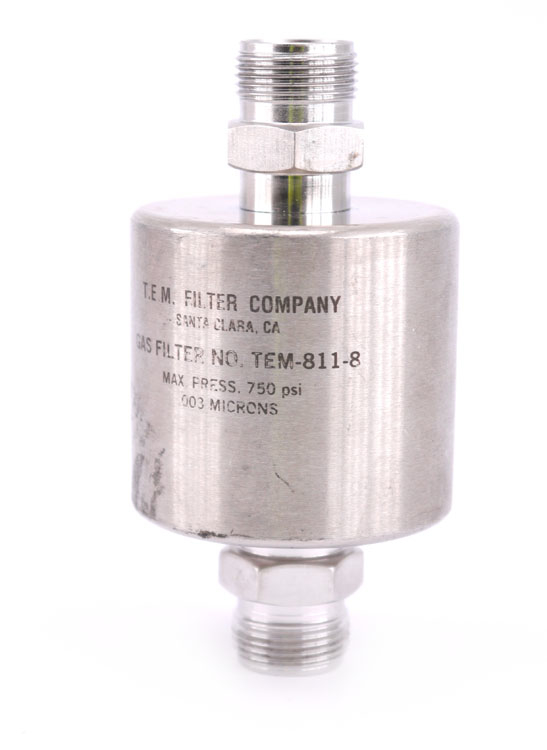 Image 27: TEM 811-8
gas filter 0.003 micron
Gas Needle Valve The gas needle valve acts as the main flow regulating valve for the Deuterium line. The type SS-SS4 Swagelok fine regulated gas needle valve with 1/4" male NPT connectors is shown in image 28: 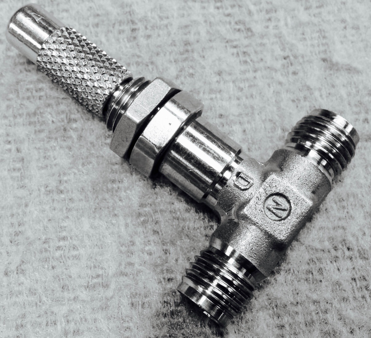 Image 28:
Swagelok-Nupro SS-SS4
fine regulated needle valve
The flow to be regulated by the needle valve must be very small and the best choice of Swagelok fine needle valves is the SS-SS4 type metering valve with a Cv value of 0.004 (flow factor, reference 2). Another option is to use two (coarser) needles valves in series. The flow factor of 0.004 is measured at the valve maximally open. This particular metering needle valve has fourteen turns from maximally open to fully closed and assuming that the flow reduction is almost linear over a range of minimally ten turns we expect that the flow factor ranges from 0.004 (open) to < 0.0004 (almost closed). Image 29 shows the actual curve for this type of metering needle valve and confirms our expectation.  Image 29: Flow Coefficient versus Turns Open for SS-SS4 Valve (© Swagelok) The graph shows clearly that we will be controlling the flow of our Deuterium gas into the Fusor only in the first two or three turns of the valve. Adjusting the needle valve to the required flow of approx. one standard milliliter per minute can take some time. Therefore, a stop valve preceding the needle valve in the line can be used to shut off the Deuterium supply while the flow regulator is kept at the set flow. For a next Fusor run the stop valve can be opened, possibly followed by some finetuning of the needle valve only. This may save time and Deuterium gas. As main shut-off and stop valve a Swagelok-Nupro SS-8BK-1C pneumatic bellows valve with 1/4" male NPT connectors will be used in combination with a 24V DC bidirectional pneumatic solenoid valve for controlling this single acting bellows valve (image 30):  Image 30: Swagelok-Nupro SS-8BK-1C pneumatic bellows valve The Swagelok-Nupro SS-8BK-1C pneumatic bellows valve is single acting with a conical seal of PCTFE, it has a Cv value of 0.96, an air displacement of 13.6 cm3, a temperature rating of -23 to 148°C, a pressure rating of 2.7 to 10.3 bar and it is normally closed (NC). Flow Meter An indication for the proper regulation of the gas flow in our system is given by a Wallace and Tiernan NPXF 142 gas flow meter with a range between 0 to 30 cc per minute (image 31):  Image 31: Wallace and Tiernan Gas Flow Meter (source: Supplier) The Wallace and Tiernan gas flow meter works on the principle of a floating sphere in a uniformly slightly tapered and calibrated tube. The tube has a length of 75 mm (3 inches), which can withstand a pressure of up to 200 psig (13.8 bar) and a temperature of up to 93°C (200° F). The connectors are 1/4" NPT. The calibration of the scale of the Wallace and Tiernan flow meter has originally been made for a flow of water. The conversion factor to be used when using Deuterium gas is 0.26. This means that the desired reading for Deuterium must be multiplied with 0.26 to find the resulting equivalent flow on the H2O calibrated scale, e.g. a required flow of 1 sccm of Deuterium is on this flow meter a reading of 0.26! Mass Flow Controller A mass flow controller is an optional extra for the Deuterium supply line to the reactor and it is therefore not strictly needed. An advantage can be that applying a mass flow controller enables to set and control the Deuterium flow at a distance, by means of a specific control unit or by means of a computer with a specific program or a more general program like LabView. The mass flow controller can provide an extremely accurate control over the gas flow into the vacuum chamber. Mass flow controllers (MFC) exist as a single control unit or in one housing combined with an electromagnetically controlled vacuum valve. Correct operation of an MFC occurs only when a sufficiently high pressure is present at the entrance port of the controller. This makes an MFC more useful in a Fusor system which operates with a pressurized lecture bottle of Deuterium gas than in a Fusor which is connected to a pressureless heavy water electrolysis system. An example of a mass flow controller, a Bürkert 8711 MFC (reference 3), without an integrated vacuum valve, is shown in image 32.  Image 32: Mass flow
controller
The MFC should ideally be calibrated for hydrogen and be able to deliver a flow with a minimum quantity of 1 SCCM (standard cubic centimeter per minute), which is the flow of Deuterium that a Fusor requires. The MFC as shown in the images has a capacity of 50 standard liters per minute and has been calibrated for Hydrogen as indicated on the label (image 33). Because the MFC of image 32 has no integrated controller, it is factually only a mass flow meter (MFM) 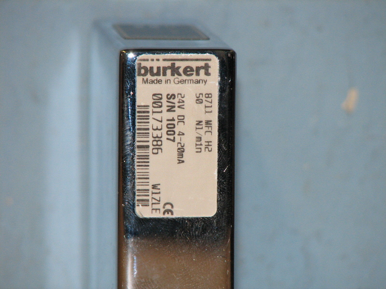 Image 33: Mass flow
controller for 50 standard liters per minute of hydrogen
The nominal flow rate of the Bürkert 8711 MFC, i.e. calibrated for 50 standard liters per minute, is a flow far too high (a factor 5x10⁴!!) for a Fusor but the actual flow can be set, ranging from 0.01 l/min H2 to 500 l min H2, by means of an external controller unit or through a program running on a connected computer. The lower limit of 0.01 l/min is still a factor 10 too high but some experimenting could be done to get the right value. The nominal flow value of the MFC is the maximum flow value calibrated which can be controlled. The nominal flow range defines the range of nominal flow rates (full scale values) possible. The mass flow controller needs additional equipment in order to control the flow of gas, such as a Multichannel Program Controller (MPC) unit, a solenoid valve, 24V power supply and cabling between these items. In order to get the low flow of Deuterium required for the Fusor, a solenoid valve should be chosen with a small orifice, preferably not exceeding 2 mm diameter. Instead of an MPC, an RS-232 connection (image 34) can be made between the MFC and a (Windows operated) computer and the MFC can be operated through a program that is available from the manufacturer (reference 4). Additionally a MFC Driver DLL for serial communication with the device may be required and can also be downloaded from reference 4. Operating manuals can be found in reference 5. Note: reference 5 also gives access to items from references 3 and 4. 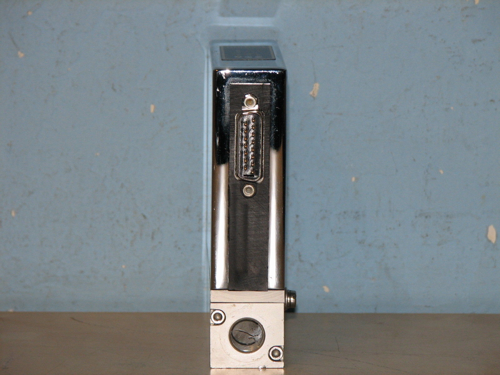 Image 34: flow- and
computer connection ports on the MFC
The status of operation of the MFC is indicated on the housing (image 35):  Image 35: LED
indicators on MFC housing
A more suitable MFC was however found, the Hitachi made SAM FANTAS, model SFC1480FA MC-4UGL, calibrated at a maximum flow of 20 SCCM for Hydrogen gas (image 36): 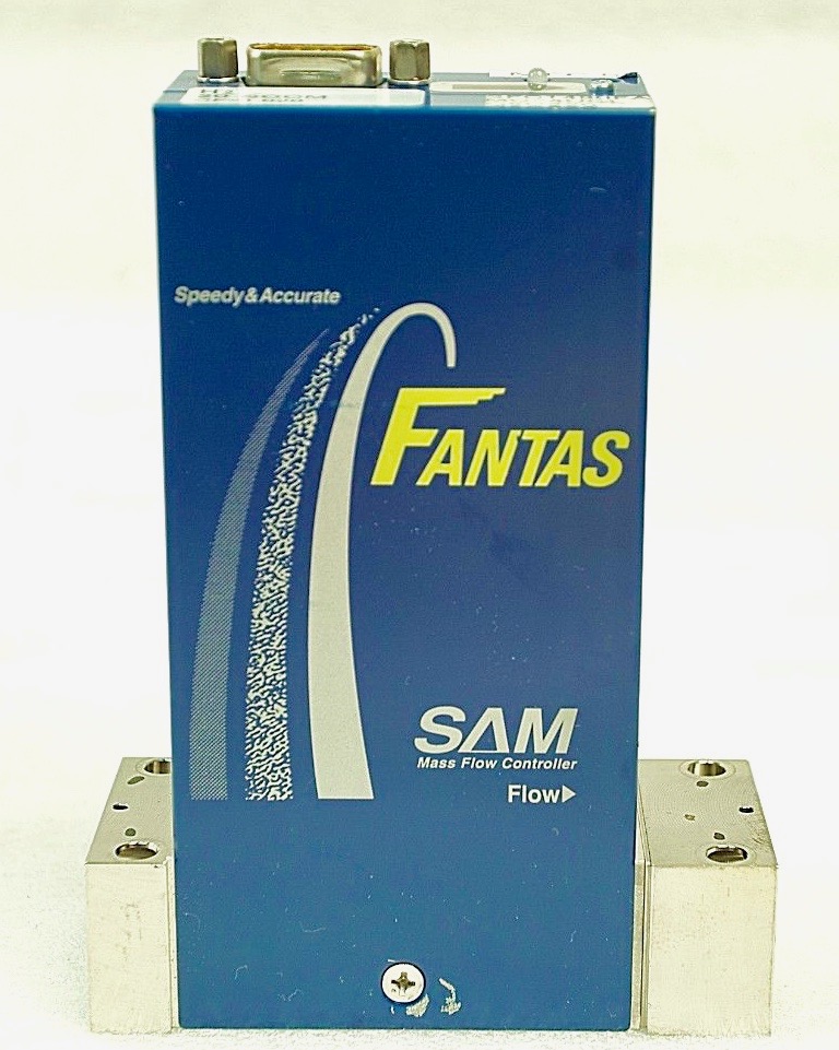 Image 36: SAM FANTAS MFC (source: supplier) According to manufacturer's specifications the minimum flow for this MFC is 1 SCCM at an inlet operation pressure of 0.05 to 0.3 MPa. The MFC is an IGS (integrated gas system) model with a metal seal and normally closed (NC), 1/4" female in- and outlet connectors and a D-sub 9-pins (Valve open/close-connected to ±15VDC) connector (image 37):  Image 37: Top of MFC with D-sub connector (source: supplier) The layout of the D-sub connector pins is as follows: 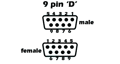 Image 38: D-sub Connector Pin Numbering
Table 1: D-sub Connector Pin Layout
Notes: 1) ALL COM lines are connected inside of the MFC. 2) Valve open/close Inner valve will be fully open when +15VDC is applied to pin #1 and fully closed when -15V is applied to pin #1. Lacking an appropriate controller we will have to construct a device consisting of a control device delivering a variable power of 0.1 to 5VDC on pin 6 for the flow setpoint control, in combination with a power supply capable of delivering positive and negative 15VDC with a maximum current of 100 mA (abs. max. 120 mA). The flow signal output on pin 9 varies from 0 to 5VDC and can be used for observing the output. A simple way to achieve a kind of controller is by using an old favourite, the Arduino Mini-Pro in combination with either a computer system or a LED-display and a potentiometer for the setpoint. The tasks for the Arduino will be
Capillary Input Line The capaillary tubing or input line is a coiled stainless steel tubing with a narrow diameter. It has the function to further restrict the flow of Deuterium into the reactor. The inner diameter of the tubing is 1-2 mm or less. A flow restrictor is an essential part of the Deuterium line and cannot be missed. For our Fusor we make use of a type 316 stainless steel tubing intended for HPLC columns with an outer diameter (OD) of 1/16" (1.6 mm) and an inner diameter of 0.010" (0.25 mm). The length is 9.84 ft (3 meters) (image 39).  Image 39: HPLC stainless steel tubing The advantage of using 1/16" HPLC tubing is that a large collection of couplers, reducers and connectors can be used, available from manufacturers such as Swagelok-Nupro, Parker-Hannifin, etc., which is convenient for connecting the tubing to our other components in the Fusor gas line. The flow restrictive effect (i.e. the pressure drop) of a length of SS HPLC tubing can be calculated with the Darcy-Weisbach equation.  ΔP is the loss in pressure caused by friction, expressed in Pa units, ƒ is the Darcy friction coëfficient (dimensionless), ρ is the density of the fluïdum, expressed in kgm-3 units, L is the length of the tubing, expressed in m units D is the hydraulic diameter of the tubing, expressed in m units, V is the average flow velocity, expressed in ms-1 units, For our fluïdum, Deuterium gas, we probably will have a turbulent flow for which the Darcy friction coëfficient can be calculated with the Colebrook-White equation:  ε is the wall roughness of the tubing. Convenient calculators exist in the internet to perform these calculations. For stainless steel 316 tubing the roughness is < 0.0015 mm and this yields a friction coëfficient of about 150. The density of Deuterium gas at 25°C is 0.169 kgm-3. We have a flow of 1 sccm or 0.017 scc per sec of Deuterium gas entering into the tubing with a length of 3 meters and a diameter of 0.25 mm equaling to a tubing surface of 0.20 mm2 or 0.2E-2 cm2, which therefore results in a gas velocity of 0.017/0.2E-2 cm/s = 8.3 cm/s or 0.083 m/s. Entering these parameters into one of the pressure drop calculators (e.g. reference 6) results in a calculated pressure drop of 88.7 Pa (0.67 Torr) in our system. For a length of HPLC tubing of 50 cm the pressure drop will be 14.778 Pa (0.11 Torr). Please note that this result is rather inaccurate due to assumptions (e.g. turbulent flow) and due to deviations from the ideal circumstances (e.g. a too narrow inner diameter). Why is this supposed to work? Because in the Fusor.net forum a restricting orifice has been constructed consisting of an injection needle of 1 inch length and 0.21 mm inner diameter, which held a wire inside with a diameter of 0.18 mm. The difference between the surfaces of the injection needle and the wire is the effective surface opening for the gas flow, or 0.01 mm2 The surface of the HPLC tubing is 0.20 mm2  Other Components View window A view window or view port is essential to watch the process in the reactor, The window should be kept as small as possible, but not too small that the process will be too difficult to follow. Large view ports have the disadvantage that at high HV potential too much X-rays may escape from the reactor, which is a dangerous radiation for human beings. At very high (> 30kV) HV potentials it may be required that the viewing occurs indirectly by means of a mirror at 90 degrees to the axis through the window. Also, it may be necessary to apply a lead shielding around the view port and camera setup, or in some cases around the total of the reactor. The view port in our Fusor system is shown in image 40 and is mounted in a KF50 mounting with a view opening of 46.5 mm diameter: 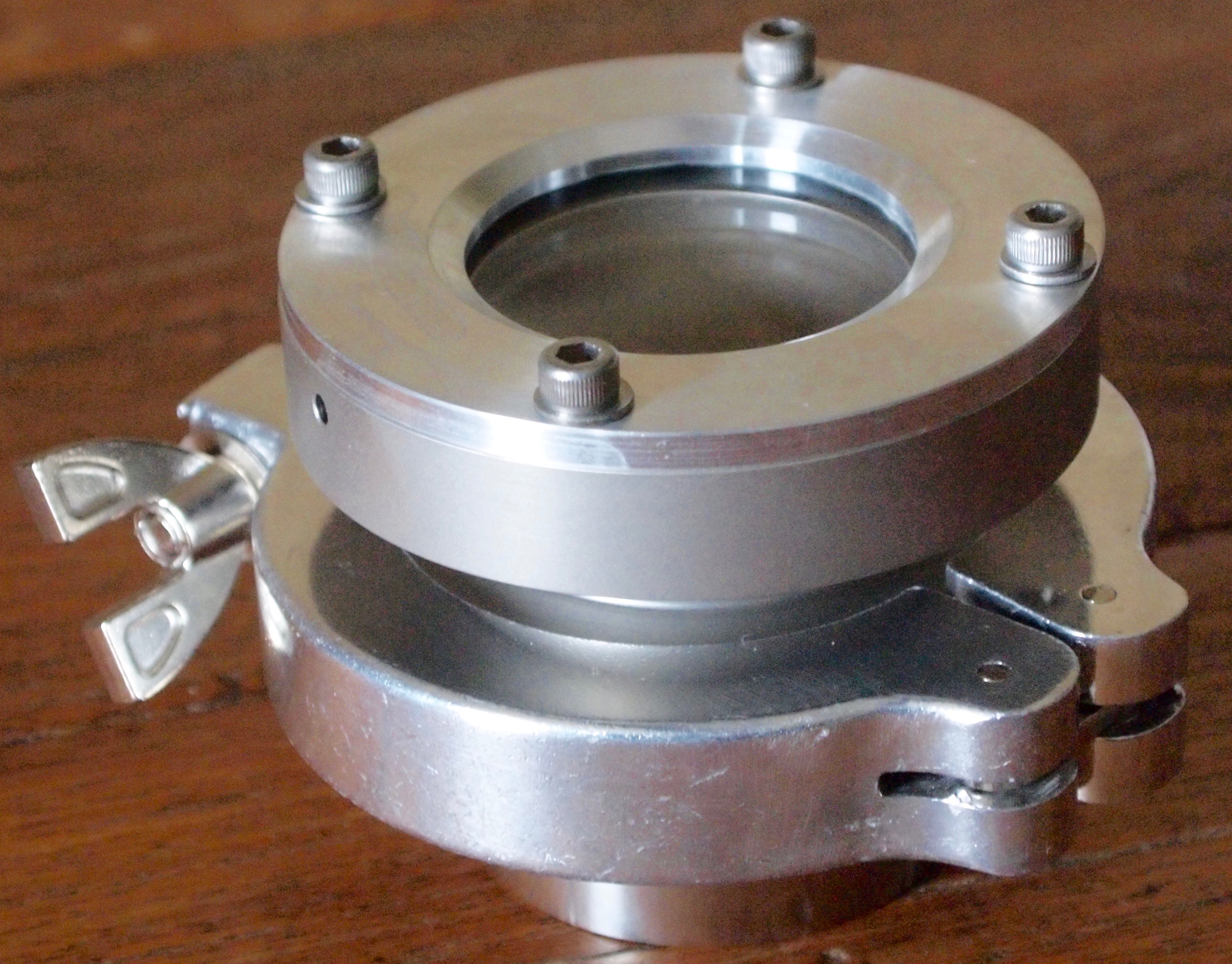 Image 40: View port
in KF50 mounting on weld stud (© FRS
2016)
The glass in view ports can be made of borosilicate glass (heat resistent), quartz glass (no coloration by gamma rays) or lead glass (shielding x-rays and gamma rays). Camera Any video camera is in principle suitable for observing the fusion process when the possibility exists to perform the observations in real time, i.e. simultaneously while recording. Also, the possibility should exist to switch off the autofocus system of the camera and to set the focus at a fixed distance. It is quite irritating when during an experiment the camera continuesly focuses for a sharp picture. A wireless connection to the (computer) monitor is not advisable due to potential interference from the Fusor HV power supply. A HD webcam might be the best option when the accompanying software permits simultaneous observation and recording and additionally permits to take stills. Very expensive camera's should be avoided because of the possibility of damage to the electronics due to gamma rays and/or hard X-rays.  |
 |
 |
 |
 |
 |
 |
 |
 |
 |
 |
 |
| References:
Ref. 1: Deuterium Line: http://tommccarthyprojects.com/gas-line/ Ref. 2: Swagelok flow factor: http://www.swagelok.com/downloads/webcatalogs/EN/MS-06-84.PDF Ref. 3: Bürkert 8711 Mass Flow Controller: http://www.buerkert.de/de/Media/plm/DTS/DS/DS8711-Standard-EU-EN.pdf Ref. 4: Operating software for Bürkert mass flow controllers: http://www.burkert.com/en/Service-Support/Support/Glossary/Mass-Flow-Communicator-communication-software Ref. 5: Operating manuals for Bürkert 8711 mass flow controller: https://www.burkert.com/en/type/8711 Ref. 6: Pressure drop calculator: http://www.pipeflowcalculations.net/pressuredrop.xhtml |
Last Updated on: Fri Jan 4 18:09:54 2019 |