 |
Fred's Fusor
Monitors |
|
| Contents of this page Introduction In this section of the website the different monitors and measuring devices are discussed that will be used in the operation of the Fusor. Vacuum For measuring and control of the pressure inside the vacuum chamber and its connecting components four devices are available:
An issue to bear in mind is the difference in units that is in use by both devices: the thermocouple controller reads its output in Torr and the ionization gauge controller reads its output in mbar. As the operation of the Fusor will require switching on the oil diffusion pump at a vacuum pressure that is just in the overlap of both devices it is essential that the difference in units as expressed by the devices is carefully observed. A most helpful guide for understanding the principles of vacuum measurement was found in: "Guide to the Measurement of Pressure and Vacuum" (reference 1).  Thermocouple The thermocouple vacuum sensor and its analogue gauge controller is of the Edwards brand, model TC-1 (Images 1 and 2). The controller permits setting of the current and the instrument can measure pressures from ambient pressure (760 Torr) down to about 10-3 Torr (1 micron). Thermocouple gauges are not very accurate but they will give at least an indication of the pressure in the foreline, which is essential to know before starting the oil diffusion pump . There was no other way to test the instrument than connecting it directly to the suction (inlet) port of my single stage Leybold-Heraeus rotary vane vacuum pump, which according to its specifications can obtain an ultimate partial pressure of 3*10-2 Torr (30 micron). After degassing the pump and pumping for one hour at the sensor gauge a pressure was reached of 8*10-2 Torr (80 micron). Considering the age of the pump and its wear the assumption was made that the thermocouple gauge could be considered as fairly accurate.   Image 1 and 2:
Edwards TC-1 Thermocouple vacuum gauge
 Hot Ionization Gauge For measuring the final high vacuum in the reactor a hot ionization gauge will be used, a Leybold-Heraeus Ionivac IR 10. In combination with the IM 110D control unit this gauge can measure down to a lower limit vacuum of 5*10-7 mbar (7.5 x 10⁻⁸ Torr) but it can only start measuring at an upper limit vacuum of 1 mbar (7.5*10-1 Torr). Therefore it is advised not to power up this gauge until a vacuum has been obtained greater than 10-2 Torr or (even better) more. The IR10 is a gauge with a nine pin connector at one side and an open KF 40 vacuum connector at the other side (Image 3). The gauge has to be connected to a Heraeus Leybold Ionivac IM 110D controller (Images 4 and 5), but the connecting cable is (of course) missing. No hope exists that ever the proper cable for this unit will be found, because all the equipment is aged surplus gear (though working!).  Image 3: Leybold-Heraeus
IR10 hot ionization
gauge
  Image 4 and 5: Leybold-Heraeus
IM 110D, front side
The IM 110D controller was shipped from the USA and therefore after arrival the case was opened to check if it was set at the proper 230V for Europe, even despite the fact that the instrument came with a cable and plug suited for Europe. It appeared that the instrument was set for 230V, which could be done with a small piece of pcb, just behind the mains transformer, that could be inserted in different ways, thus enabling use at different voltages. When the casing was open the opportunity was used to check for the connections at the gauge connector at the back of the unit (image 6). 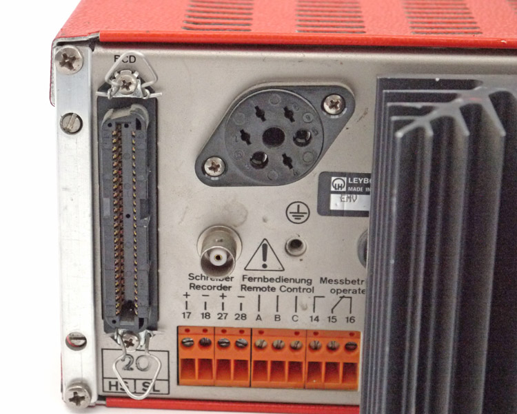 Image 6: Heraeus
Leybold Ionivac IM 110D, back side
 Image 7: Connector
from image 6 (tilted in horizontal position)
 Image 8: schematic
layout of IM 110D connector with colour codes of attached wires ©
FRS 2014
The black, round connector (image 6, center, top, it looks like a tube connector, and image 7, same connector but now tilted horizontally) is for connecting the IR10 hot ionization gauge. It has only four wires connected at the following pins (Image 8 schematic layout of pins as looked on the backside):
The IM 210D controller has an identical output socket for the connection of the gauge and it seemed to me that the manufacturer had no really good reasons to make the connections very different for almost similar controllers. First of all Oerlikon, Leybold and Heraeus are Swiss/German manufacturers and (though this is very generalizing) manufacturers of that origine usually work very organised (Ordnung muss sein!). Let's make a comparison about found (IM 110D see Image 8) and listed (IM 210D) connections for the cable plug:
nc = not connected
Table 1: Comparison
connectors IM110D and plug IM 210D
Table 1 unfortunately does not show any equivalency for the colour of the wires and the choice of pins except for the ground connector at pin 4. Because the same connector and plug are used on both the IM 110D and the IM 210D and because different types of gauges with different voltage requirements are used on both, it could be assumed that in order to prevent damage to a sensor or controller when a wrong type of gauge is connected, precautions have been taken in wiring the connectors and plugs. Furthermore it could be assumed that the colour coding is adhered to as much as possible as well as the position of the connections on the plug and connector. A presumption is now that for the IM 110D the cathode is connected to connector pins 1 and 6 (switched positions compared to the IM210D) and the anode could be connected to pin 3. A test with a multimeter should confirm if this presumption is correct. In order to find out if the presumptions could be correct, it was decided to measure the voltages over the wires connected to the connector (common and + refer to the probes of the DMM): 1) blue wire at common; green wire at + → 103V DC idem but button "emission" activated → 100V DC (Note: relay activates and display shows 0.0E-4) idem but button "ausheizen" activated → 103V DC 2) blue wire at common; yellow wire at + → -14 - -18V DC idem but button "emission" activated → -14 - -18V DC (Note: no relay activation) idem but button "ausheizen" activated → -14 - -18V DC 3) green/yellow wire at common; blue wire at + → 0.3 - 1.1V DC idem but button "emission" activated → 0.3 - 1.1V DC idem but button "ausheizen" activated → 0.3 - 1.1V DC 4) green/yellow wire at common; green wire at + → 107.1V DC idem but button "emission" activated → 107.1V DC idem but button "ausheizen" activated → 107.1V DC 5) green/yellow wire at common; yellow wire at + → -14 to -18V DC idem but button "emission" activated → -14 to -18V DC idem but button "ausheizen" activated → -14 to -18V DC According to the manual for the sister controller Ionivac IM 210D the "emission" push button should be activated when the pressure is below 10-2 mbar. The emission mode is stopped when the "emission" push button is activated again or automatically when the pressue exceeds 10-2 mbar. The LED in the display is activated when no sensor is connected and this means that the circuit one way or another "measures" the presence or absence of the sensor, i.e. by means of an interruption in the cathode circuit. The emission is kept constant with a precision of 2%. From the measurements the voltage of 100V could be attributed to the anode, but the cathode potential of 2V and the cathode heater voltage of 2V arer missing and the degassing voltage is another mystery. Should the day arrive that the coonections of the controller are clear than a cable shall be made to connect the controller with the gauge. Because we do not have the original plug that fits the connector on the controller a new connector and plaug shall be installed at the back of the controller. For that purpose we shall use a 12 mm diameter, 5-pin aviation connector and plug as shown in image 9:  Image
9: connector and cable plug for vacuum controller
 Leaving the controller we have a look now at the gauge as it is a bit difficult to understand how a four wire connector connects to a nine pin gauge though a closer look at the nine pins of the gauge could explain how they connect to the inner grids and filaments. We shall start the analysis of the IR10 gauge with listing its specifications as derived from the February 1986 published operating instructions See reference 3. Specifications of IR10: According to reference 2 the IR10 has an electrode configuration system of a concentric Triode. The material of the cathode is made of Iridium with a Thoria coating and the anode has been made of a Nickel ion catcher with a Molybdenum gitter. The maximum bake-out temperature without the plug is 400°C and the X-ray limit is < 1*10-7 mbar. The collector potential is 0V and the cathode potential is +10V. The anode potential is +100V and the emission current is 0.016 mA. The cathode heater current is 4A and the cathode heater voltage is 2V. The maximum power dissipation during degassing (By electron bombardment) is 25mA/600V. Analysis: The difference between a concentric Triode gauge and a more commonly used Bayard-Alpert hot cathode ionization gauge is that the Bayard-Alpert gauge is a Triode gauge turned inside out (ref. 1, page 32), i.e. the hot filament is outside the cylindrical grid. As a result of this different configuration fewer X-rays will strike the collector (emitted by electrons from the ionised gas hitting the grid), resulting in a lower pressure limit than for the Triode gauge.  Image 10: Triode
Vacuum Gauge Configuration (source: Fredericks Company)
As can be seen in image 10 the Triode vacuum gauge uses 4 electrical connections: two for the filament, one for the grid and one for the collecting electrode. In order to determine the pins in the IR10 a simple test was performed by measuring the resistance over the different pins. The pin configuration is shown in Image 12. The results of the measurements can be found in table 1:
Table 1: Resistance
over pins in Ohm (~ = no conductance)
The results from the table could be somewhat questionable when considering the values found: lower than and equal to 0.5 Ω, which is usually equivalent to the resistance value for a conducting wire. However, it may be concluded that in one way or another pins 1 and 7 and 1 and 9 are connected, as well as pins 3 and 7, and pins 3 and 9, and pins 7 and 9. From the specs it is, however, known that the IR10 is a concentric Triode, i.e. the cathode, grid and anode are placed as shown in Image 11 (please note that the values for the cathode, anode and collector potentials are arbitrary): 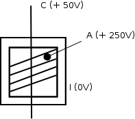 Image 11: Concentric
Triode schematic layout © FRS 2014
The central cathode (C) is concentrically surrounded respectively by the anode (A) and the ion collector (I). There is, however, one characteristic in the specifications that raises a red flag: the upper vacuum limit is 1 mbar (7.5*10-1 Torr), which is rather uncommon for a traditional hot ionization gauge. Moreover, Triodes as hot ionization gauges were popular between about 1920 and 1955 and thereafter replaced by Bayard-Alpert type of gauges for reduction of the X-ray effect and achieving a higher vacuum limit. Why should a reputable manufacturer as Leybold Heraeus keep a Triode in its 1986 (and 2002, see below) sales program when they have long before that shifted to Bayard-Alpert gauges? The answer is probably because they wanted to sell a gauge that covers the vacuum range from a relatively high pressure, 1 mbar, up to near ultra high vacuum, 5*10-7 mbar. The requirement to make a Triode measure at a relatively high pressure is achieved by changing the order of the concentric electrodes from CAI to CIA (from the inside out), i.e. in a high pressure hot ionization gauge the central cathode is surrounded by a cylindrical collector, followed by a cylindrical anode. See reference 4. and reference 6. This further confirmed by reference 5, which was surprisingly found on the internet when searching for the sister gauge IE10, where it is also stated that in order to facilitate measuring at higher pressures (up to 1 mbar) the cathode is resistent to higher oxygen contents of the gas. This has been achieved by constructing the cathode as a "non-burn-out" cathode by using an yttrium oxide coated irridium strip as the cathode. Additionally, in order to obtain a linear characteristic up to pressures of 1 mbar (linear dependancy of the ion current to the pressure) a resistor of several megohms has been added to the anode circuit. Furthermore, In these operating instructions is also clearly stated: "Both gauge heads are almost identical. In the neck of the IR 10 there is an additional wire mesh screen which is at ground potential. The net-like electrode (anode) of this nude gauge head has an oval shape for physical reasons". 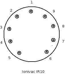 Image 12: Pin layout
of the IR10 © FRS 2014
Taking a closer look now at the IR10 we see that the central cathode (C) is connected to pins 7 (bottom of the cathode) and 1 (top) and 9 (top), pins 1 and 9 are connected by a bridging strip and that makes sense at a resistance value of 0.3 Ω, whereas the bottom of the cathode (pin 7) is connected through a coiled wire to pin 3. From the sales brochure (ref. 5) we know that the net-like electrode is the anode and we see this structure as the outside concentric cylinder in the IR10, which confirms that the layout indeed is CIA. The anode (A) is connected to pins 2 and 8 (common) and the ion collector (I) is connected to pins 4 and 6 (common). Pin 5 is connected to a gitter that has been placed at the exit opening of the tube and which, again conform ref.5, is to be connected to ground. The values measured in table 1 make sense in so far that for the cathode according to the specs of the IR10 a heater voltage has been specified as 2V and a heater current of 4A and this yields a resistance of 0.5 Ω (pins 7 and 9 + 1). The collector potential has been specified as 0V and this means probably that it is connected to ground (pins 4 and 6). The anode pins (2 and 8) also yield a resistance of 0.5 Ω, which makes sense because both electrodes are connected thorugh a bridging strip. At a potential of 100V this probably means that both pins are connected to +100V. That could probably explain an emission current of 0.016 mA. There is another specification for the IR10 that we yet have not dealt with so far: the degassing power dissipation of 25 mA/600V. The controller IM 110D indeed has a push button for degassing the gauge, but how does that connect to the gauge? An assumption is made in Image 13. 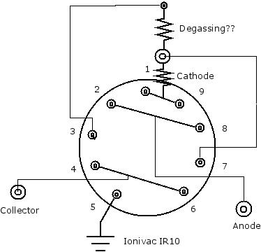 Image 13: IR10 with
presumed connections © FRS 2014
Having arrived this far I have to admit that the issue of the IR10 has kept me busy for almost a week! Of course not continuously, but every spare hour was used. This concludes so far the analysis of the IR10 and of all its pins but it remains still unknown how to connect them to the IM 110D controller! When the connection problem is fully resolved the next step then shall be to find a suitable new plug and connector for the IM 110D and to make a cable to connect to the IR10. Fortunately it appears that the nine pin male connector at the IR10 fits onto a standard noval tube connector. See Image 14. The noval tube connector is made of a good insulating ceramic material. The next step shall be to make or find a cover that protects the soldering lips at the bottom of the noval tube connector.  Image 14: Noval tube
connector (9 pin)
Image 15 shows the IR10 gauge with the noval connector attached:  Image 15: IR10 gauge
with noval connector (©FRS2014)
 Cold Ionization Gauge A cold cathode ionization high vacuum gauge of the inverted magnetron type was obtained, a (Pfeiffer) Balzers IKR 050 (image 16):  Image 16: (Pfeiffer)
Balzers IKR 050 Cold Cathode Ionization Gauge (© taste199)
The specifications for the Balzers IKR 050 gauge are:
A cold cathode ionization gauge has a measurement circuit based on crossed electromagnetic fields and have been developed according to principles like Laferty, Penning, magnetron and (single or double) inverted magnetron. The measuring circuit is relatively simple, as shown in image 17:  Image 17: Penning vacuum
gauge principle (© FRS 2015)
The cold cathode gauge contains a hollow anode located inside two cathodes; the cathodes/anode array is surrounded by a strong (circular) permanent magnet. A DC high voltage is applied between anode and cathode. A series resistor limits the maximum current drawn. The variation in the current drawn is related to the vacuum present. In theory it is relatively easy to build a metering controller once we know the relation between pressure and current. This relation between pressure and current obeys the relationship igauge = k.Pn
wherek = constant P = pressure n = constant ranging usually from 1.00 to 1.15 The equation is valid for a pressure range from 10-8 Torr to an upper limit of about 10-3 Torr, depending on the series resistor used. Advanced cold cathode gauges, based on the inverted magnetron priniple, can measure a vacuum as far down as 10-12 Torr. When we do not know the constants for a specific cold cathode gauge the only other method to establish this relation is to determine it by calibrating the gauge against a second, calibrated gauge. Note: a special warning is given here for those who intend to build the circuit just as simple as shown in image 17. It is quite possible to mount a suitable µA meter into a high voltage circuit, but special precautions are required to insulate all high voltage parts from the operator. Commercial cold cathode controllers usually have strictly galvanically separated circuits between the high voltage supply and their read-out and control sections. A (theoretical) indirect way to measure current in a high voltage line is to determine if it can be done with a hall effect transducer, e.g. the MLX91206 (USD 4.52), which comes in a SOIC8 package. Hall effect transducers measure the magnetic flux around a conductor carrying a current and they do that within a frequency range of 0 to 90 kHz. However, hall effect transducers work only with relatively high currents (500 mA upwards). This limitation may be overcome by applying a coil around the sensor for increasing the magnetic field.  Image 18: Hall Effect
Transducer in Coil (© Melexis NV)
Image 18 shows the MLX91206 IC on a circuit board inside a coil. The coil is made with a thin HV wire (insulated up to max. 10 kV), e.g. UL3239-24-10KV-124, a 24 AWG extruded modified FEP wire with 0.5 mm core diameter and 1.50 mm outer diameter. This size of wire is fully suitable (up to 3.5 A for a single core) for the low currents (< 700 µA) that are generated by the cold cathode sensor. Preferrably, the coil for the hall sensor needs to be shielded with mu-metal to improve sensitivity and to decrease influences form external fields. A factor to be taken into account is if the HV circuit will tolerate the inductance caused by the coil as we may need hundreds of turns before we get a sufficiently high magnetic flux for the IC. For example: with the IC mounted on a printed circuit board the dimension of the pcb intruding into the coil is 5 mm wide and 10 mm long (the chip on the pcb is 4.80 x 5.84 mm). The coil therefore will have an open, inner core diameter of 7 mm. For 96 turns of the wire mentioned, we use a coil length of 12 mm storing 8 turns of wire on the first layer and a height of 18 mm for storing 12 layers on top. The outer diameter of the coil is than 7 + 18 = 25 mm. According to reference 7 such a multilayer air coil will have a calculated inductance of 125 µH. When we continue winding and add another 96 windings on top of the previous windings the coil will have a calculated inductance of 899 µH. Another method to measure the current indirectly is by means of a high voltage optocoupler in combination with an operational amplifier (opamp) but the disadvantage is that the ooutput of an optocoupler is not linear. It was then decided to find out how the issue of measuring a low current in a high voltage line was tackled by the trade. Therefore an old cold cathode controller was cheaply obtained through eBay. The instrument is a model VM 301 measuring device built by VEB Hochvakuum Dresden in the former German Democratic Republic (DDR) (image 19 and 20). 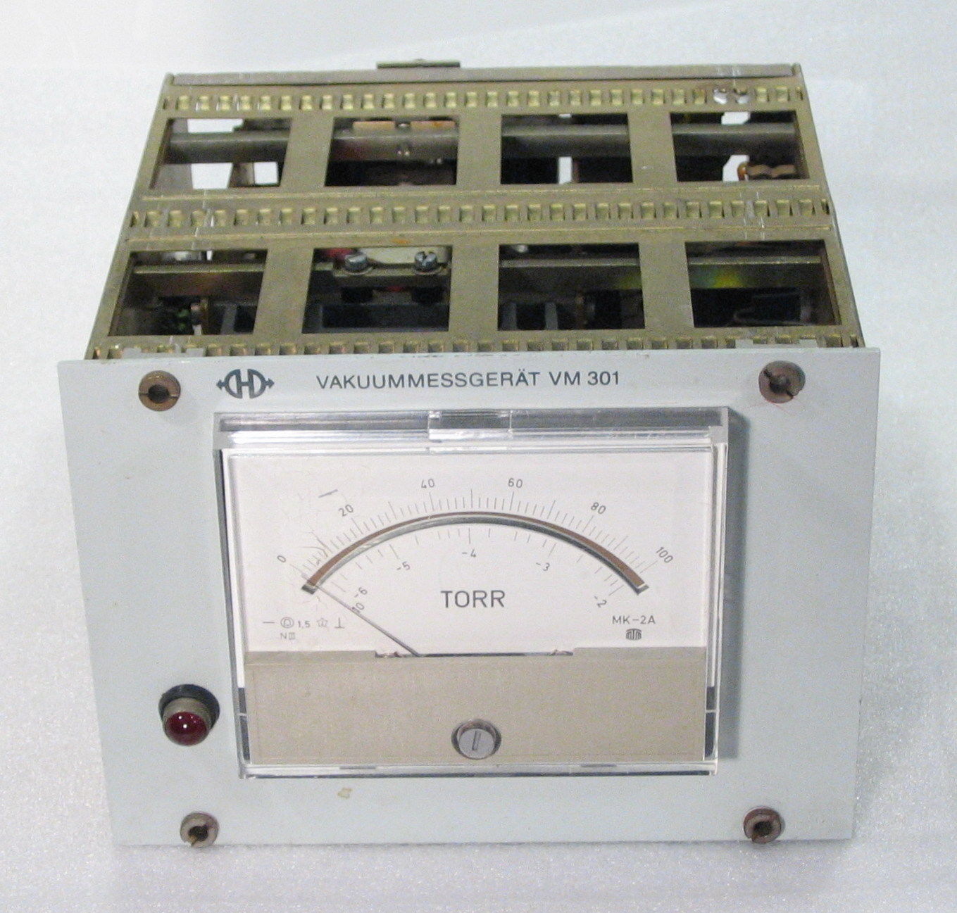  Image 19 and 20: Penning
Vacuum Controller VM 301 by VEB Hochvakuum Dresden (©
ojau_1)
The fact that the instrument was buit in the DDR means that it has been built somewhere between 1960 (the year that the company was founded) and 1989, the year that the German Democratic Republic ceased to exist. Though the company still exists under the name HVD Vakuumanlagen & Maschinenbau Dresden GmbH, no information, specifiations and manuals for the VM 301 can be obtained. The device outputs a stable 2000V through a large BNC type connector (13 mm outer diam.) and has a separate 0 to 10V output rated at 1 mA. The analogue meter reads from 0.01 to 10-6 Torr (lower scale) and 0 to 100 (upper scale). The measuring range and the output at 2 kV indicate that the instrument presumably was built for a Penning sensor. Shortly after finding the VM 301 controller an incomplete Pfeiffer TPG 300 total pressure gauge controller became available and could be acquired for a rather low price, suiting the budget. The TPG 300 is a modular controller, which consists of a basic unit with plug-in boards for Pirani and cold cathode gauges, as well as for interfaces and relays (image 21 and 22).   Image 21 and 22: Pfeiffer
TPG 300 Total Pressure Gauge Controller (© tbble94)
The TPG 300 in images 21 and 22 has the plug-in modules PE 300, BG546930-T for an IKR type cold cathode gauge and IF 300R, BG441250-T, a relay card for which the matching female connector is known as HARTING 09062152821. Missing is a PI 300D or PI 300DN module for a Pirani gauge (note the empty bay in image 22), which is essential for operation of the unit as it controls also the PE 300 module. Therefore, I had to search for a Pirani gauge module, the TPR 010 or TPR 018 Pirani gauge and the cable....... Furthermore, a coax cable with two SHV BNC connectors had to be made for connecting the IKR 050 gauge to the controller. A female and a male SHV BNC connector were obtained from a supplier in China and the coax cable used was an RG 8 cable, which accepts high voltages. Pirani Gauge The Pirani gauge module PI300D for simultaneously connecting two Pirani gauges (image 23 a) was found just a few days later after receiving the TPG 300 controller, which controller appeared to be never have been used and was tested to work immaculately. Of course, no cable came with it and making a cable for connecting a TPR 010 gauge to the PI300D module is far more complicated than making a cable for the IKR 050 gauge and the PE 300 module. The latter cable consists, as mentioned, of an RG 8 coax cable with two SHV BNC connectors, but the Pirani gauge cable is a totally different challenge consisting of a four wire cable (4 x 0.34 mm2) with screening and as connectors on the gauge side a female connector LEMO FGJ.1B.304 and on the module board side a male 6-pin connector Amphenol C91E and additionally a ferrite clamp on the cable at maximally 2 cm of the Amphenol module connector. Both connectors have crimp terminals and therefore require crimp pliers, e.g. Amphenol FA0100-146. It was therefore quite a relief to find a Balzers TPR 010 Pirani gauge complete wiith the cable (image 23b).    Image 23 a, b and c:
Pirani Gauge Module Pi 300D, TPR 010 Gauge and Cable and TPG 300
with TPR 010
(© Parts4Parts NL / © Smiples CH / © FRS2015) However, the PI300D connector on the Pirani gauge cable appeared not to be of the required type and it also appeared that Amphenol C91E 6-pin connectors are now obsolete. Therefore an Amphenol C91D 6-pin connector was ordered (which also does not fit, but has at least the proper 6-pin insert) and parts of the existing and the new connectors were merged. Because the new 6-pin insert had to be soldered onto a cable it was decided to replace the rather short cable that came with the Pirani gauge by a new 15 m long cable (6 shielded wires of which 4+1 are used). The longer cable (with higher resistance) now required calibration of the gauge/module combination, which was executed at ambient pressure (1013 mbar or 760 Torr). Image 23c shows the TPR 010 Pirani gauge connected to the PI300D module in the TPG 300 unit and measuring ambient pressure at 7.6 x 10² Torr. The method of operation of a Pirani gauge is based upon a heated Platinum or Tungsten wire, diameter 0.02 mm. of which the resistance drops when heat is removed by gas molecules hitting the wire. The resistance is kept constant by a sensitive Wheatstone bridge configuration. Keeping the resistance constant requires a change in the current, which is measured and converted to a vacuum pressure output. The accuracy of a Pirani gauge is better than ±10% when heating up of the gauge housing is measured and compensated by the controller. Pirani gauges are gas dependent, i.e. the results when measuring in a Hydrogen atmosphere will be different from those measured in a Nitrogen atmosphere. Prior to operation Pirani gauges need to be calibrated at known ambient pressure and at a known low pressure. The philosophy behind the TPG 300 unit is that it measures and controls the pressure in a vacuum system from ambient pressure (760 Torr) down to 1.5 x 10⁻⁹ Torr by automatically switching from the connected Pirani gauge(s) to the connected cold cathode gauge when the vacuum increases. At the same time through the relay module it can switch on or switch off components in the vacuum system at preset pressure values.  Neutron Detector and Counter For demonstrating that fusion actually takes place it will be essential to measure the presence of fast neutrons, which are formed as the by-product of the D-D reaction. Fast neutrons as such cannot be detected by the single Boron- or Helium-3 detector setup, but moderation of fast neutrons will be required. Moderation of fast neutrons means that the neutron energy is reduced to that of thermal neutrons and this is accomplished by surrounding the detector with a moderator, usually 5 cm of paraffin wax, water or HDPE. A thermal neutron is a neutron which has the same energy and moves at the same velocity as a gas molecule does at a temperature of 20°. Free neutrons have an mean life time of 885.7 ± 0.7 sec, which is just under 15 minutes, and they decay by beta-decay, the emission of an electron and an electron anti-neutrino to become a proton. Thermal neutrons (0.025 eV or 4.0×10⁻²¹ J or 2.4 MJ/kg) have an average velocity of 2200 m/sec. In vacuum a neutron therefore can travel a distance of almost 2000 kilometers before decaying. Table 2 shows fast neutron Half Value Layers (HVLs) in centimeters for a number of materials:
Table 2: Fast neutron HVL
in cm for shielding materials (reference 8)
Neutron detection can be performed by a number of techniques:
The sensitivity of the
silver foil
neutron activation method can be largely improved by placing a large
surface of silver foil in a HDPE or PET widemouth bottle which is
filled with
liquid scintillation cocktail fluid and by placing the bottle on a
photomultiplier for measuring counts. A large surface of silver foil
can be made by corrugating (with a metal corrugator) a strip of silver
foil and rolling up the strip. Place the rolled up strip in a wide
mouth bottle and fill up with β-scintillation fluid. See reference 10 and reference 11.
The reactions of interest
for
natural silver are 107Ag(n,Υ)108Ag
and 109Ag(n,Υ)110Ag.
The abundances of 107Ag and 109Ag in natural
silver
are respectively 51.82% and 48.18%. The following reactions, with half
lives and cross sections, occur at neutron irradiation for which only
the first and the second reaction are of importance due to their short
half lives and large cross sections:
109Ag+n → γ+110mAg
→ 110Cd+β- (Eβ = 2.24 MeV or 2.82
MeV)
(T½ = 24.2s, σn,γ = 89±4b) 107Ag+n → γ+108mAg → 108Cd+β- (Eβ = 1.49 MeV) (T½ = 2.42min, σn,γ = 37±2b) 109Ag+n → γ+110mAg → 110Cd+β- (Eβ=1.77 MeV) (T½ = 252d, σn,γ = 4.7±0.4b)
φ = A0/NσS where
A0 = induced activity in dps at the end of irradiation; N = the number of target nuclei, and can be calculated from the mass of element in sample (m), the abundance of target isotope (a), Avogadro's number (Na) and the target element atomic weight (AW) according to m·a·Na/AW; φ = the neutron flux (n/cm2-sec) used to irradiate the sample; σ = the cross section of the neutron absorption reaction, in units of cm2; S = called the saturation term and accounts for decay of any induced activity during the irradiation. S equals 1-exp (-0.693 ti/t½), where ti is the irradiation time and t½ is the half life of the induced radioactivity.
Examples of scintillation
detectors are:
Helium-3 detectors react by absorbing thermal neutrons, i.e. neutrons that have been slowed down by a moderating material to an equilibrium with their surroundings, yielding a 1H and a 3H ion. Helium-3 detectors have a low sensitivity for gamma-rays and that makes them the preferred choice as a neutron detector. In this section about neutron detection and counting the He-3 tube is called the neutron detector and the attached electronical equipment is called the neutron counter. From my previous work in the 1970's it was standard operations to compile the measuring intruments as a setup of NIM modules. NIM stands for Nuclear Instruments Module and a description of NIM-standards can be found in reference 12. Because these modules are easy to be found on the surplus market it was decided to use surplus NIM modules. NIM modules are the oldest specific equipment available for nuclear phenomena measurement and date back from 1969. Later, in the 1980's, a new system was created called CAMAC that was more oriented towards the use of computers in measurement. CAMAC modules are more difficult to find on the surplus market and that justifies the choice for NIM modules. CAMAC stands for Computer Automated Measurement and Control. Neutron Detector My preference of choice for a detector, as mentioned before, is for a true Helium-3 neutron detector but the only detector available from surplus was the Russian SNM-32 Helium-3 slow neutron corona counter detector with the following specifications:
Table 3:
Specifications SNM-32
This detector is NOS (new old supply) and comes from military surplus through a supplier in Bulgaria (Image 24 and 25). Sometimes references are made to this detector as the CHM-32 detector, which is identical to SNM-32, but written in Cyrillic script.  Image 24:
SNM-32
Helium-3 corona detector
 Image 25:
Typical
certificate for SNM-32 Helium-3 corona detector
The translation of the certificate can be found here. The SNM 32 Helium-3 corona detector requires a specific pre-amplifier (image 26, reference 13), which can be ordered through reference 14.  Image 26: Preamplifier board for SNM-32 detector (© gammaspectacular.com) 3He provides an excellent medium for detecting thermal neutrons due to the high capture cross section (5330 x 10-24 cm2 or 5330 barn) and a final state that consists of charged particles, as opposed to gamma rays. The reaction between a neutron and the 3He gas filling of the counter releases an energy of 764 keV: n + 3He ---> 1H
+ 3H + 764 keV
This is transmitted as kinetic energy by the reaction daughter products, a proton and a triton. 3He neutron detectors provide an output pulse for thermal neutron interactions, which is proportional to 764 keV. The charge produced as a result of the released energy ionising the filling gas is low. Therefore this charge is increased by applying a high voltage to the anode wire of the counter. The ratio of the charge at the anode wire to that initially created by the reaction is called the Gas Gain or Gas Multiplication. Increasing the applied anode voltage increases the gas gain. An operating voltage is chosen to give a sufficient gas gain for counting purposes. The setup of the neutron detector and the neutron counting equipment is usually by a 3He proportional counter being biased through a pre-amplifier, and the resulting signals are sent through a shaping amplifier to be analyzed with a single- or multi-channel analyzer or peak-sensing analog to digital converter. See Image 27.  Image 27: 3He-detector
and
counter setup © FRS 2014
The SNM-32 being a corona detector means that some additional electronical components will have to be included in and/or after the HV circuitry in order to compensate for background noise from the corona current. Additionally a discriminator may be needed after the pre-amplifier for the same reason. Experience with the SNM-32 shows that the counting efficiency of this detector is about 15%. From the specifications of the SNM-32 it is known that the corona discharge current should be less than 25 µA. For sampling counts the plateau voltage should be at least 1500 V. According to Ohm's Law for proper operation a bias resistor is therefore required of about 100 Megohm to yield a current of about 15 - 17 µA at a HV voltage of 1500 to 1700 Volt. The 100 Megohm resistor will maintain a corona discharge in the tube by means of a continuous discharge current. Any 3He(n,p)3H + 1H reaction will yield charged particles causing a change in the discharge impedance leading to a voltage pulse which is coupled out (capacitivily) into the pre-amplifier and then into the other instruments in the measuring chain. For setting up the detector/counter chain it may be necesssary to use a (preferably calibrated) neutron source, a reliable pulse generator and a (high impedance) scope to finetune the equipment. 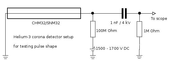 Image 28:
Helium-3 corona detector test setup (© FRS 2015)
Image 28 shows the setup for testing the pulse obtained from the helium-3 corona detector. More details are available in reference 15 and a highly detailed article about the CHM32/SNM32 slow-neutron corona detector can be found in reference 16.  Neutron Counter NIM-bin In order to use the NIM modules a power supply annex holding unit will be required, the so-called NIM-bin (Image 29 and 30).  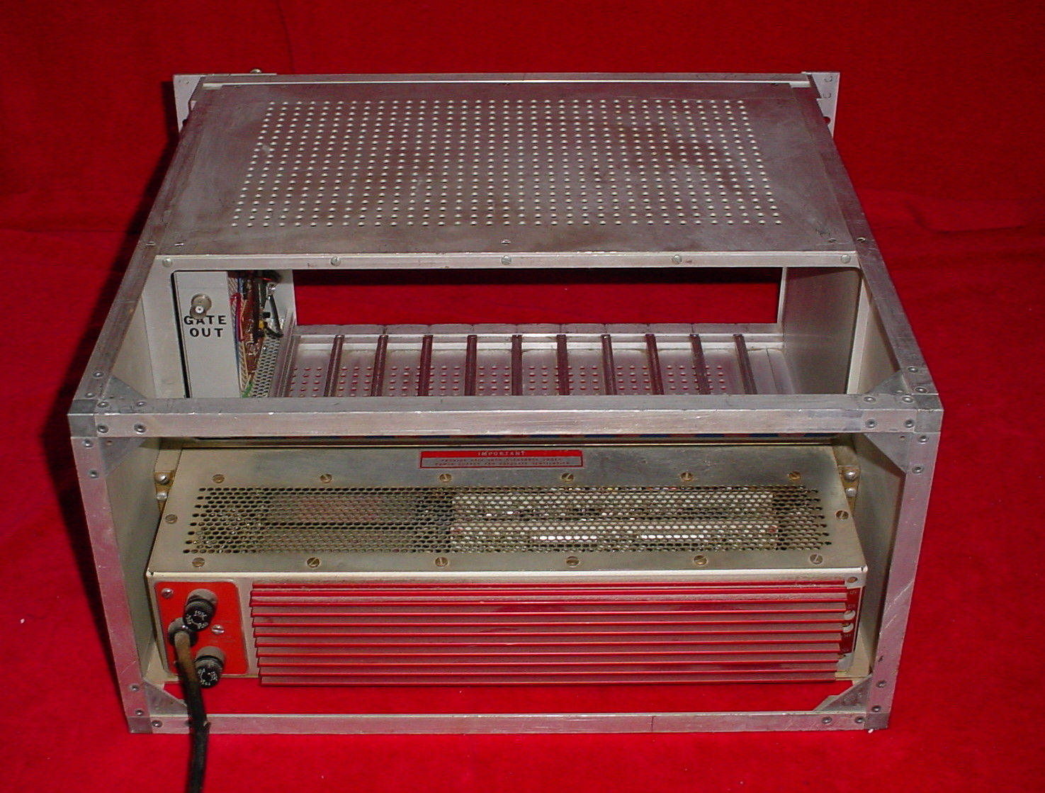 Image 29 and 30:
NIM-bin, front and back
Image 29 shows the NIM-bin from the front side with one module placed at the right, next to the fixed power outlets. Image 30 shows the NIM-bin from the back with the (heavy) power supply at the bottom. Our NIM-bin is an Ortec 401A crate with a Power Designs, Inc. Model AEC 320-3, serial no. 602170 power supply. The NIM-bin was obtained from a source in the USA and had to be converted from 115V AC input to 230V AC. The primary of the net transformer originally has two windings in parallel secured with a 3 A and a 1.5 A slow blow fuses, which are then converted to connecting in series for accepting 230V. Unfortunately after conversion and connecting to 230V supply the1.5 A fuse was blown. This meant more work to sort out the problem and moreover it took about a week to locate an AEC 320-3 schematic from around 1962. 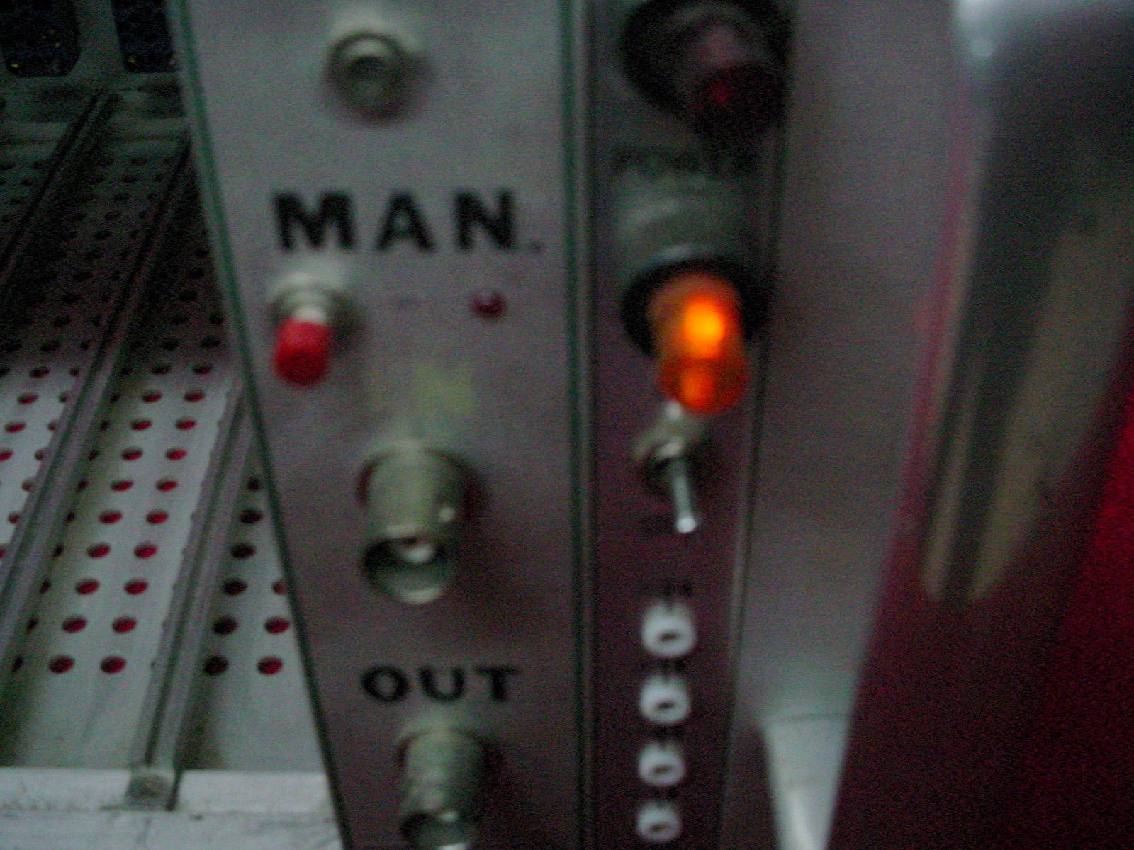 Image 31: NIM-bin,
module and power outlet
Image 31 shows the generic single module (MAN) at the left and the fixed power control and -outlet at the left.  NIM-modules An overview of the principles of a number of different NIM-modules can be found in reference 17. The following NIM-modules will be used in consecutive order for neutron detection and counting:
and/or
1. Charge sensitive pre-amplifier The charge sensitive pre-amplifier is the first module in the chain and it is directly connected to the Neutron detector. It is not a NIM-module, but either an industrial instrument or an in-house-built electronic circuit, adapted to the specific characteristics of the neutron detector. The charge sensitive pre-amplifier is connected to the shaping amplifier and the high voltage power supply. For a theoretical approach of the subject, see reference 18. An industrial instrument could be the Canberra 2006, a proportional counter pre-amplifier. This preamp converts the ionization charge from the detector into a step voltage pulse whose amplitude is proportional to the total charge collected in each event. The pulse decays with a time constant of 50 μs for presentation to a main amplifier. See Image 32. 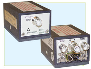 Image 32: Canberra
2006 proportional counter pre-amplifier (image source: Canberra
Industries, Inc.)
Preamp The Canberra 2006 has been used here as an example because it proved really difficult to find a suitable preamp on the surplus market. The decision to build one in our workshop is easy to make though not easy to execute due to the hughe amount of circuits that can be found on the internet. A suitable circuit was found, which is the circuit of the Ortec 109A preamp. The manufacturer provides the following specifications (reference 19): ORTEC 109A PREAMPLIFIER DESCRIPTION The 109A is an all-transistor preamplifier with pole-zero cancellation using a field-effect transistor in the input stage. The circuitry includes a charge-sensitive input loop, an amplifier stage with switch selectable gain with a 10:1 ratio, and a cable driver stage. The preamplifier is inherently an inverting preamplifier, i.e., a negative input pulse yields a positive output pulse. No pulse shaping is accomplished in the preamplifier, except for a pole-zero-cancelled 50 uSec differentiation time constant immediately after the charge-sensitive loop, for the purpose of reduction of pulse pileup at high count rate. System pulse shaping for optimization of signal-to-noise ratio will be accomplished in the subsequent main amplifier. SPECIFICATIONS Basis of Warranty ≤ 0.025 keV/pF FWHM (Ge) slope, 2.5keV FWHM (Ge) maximum at 0pF input capacity. Typical performance is given below: TYPICAL PERFORMANCE
Table 4: Typical
Performance Ortec 109A Preamp
Table 5:
Characteristics Ortec 109A Preamp
COUNT RATE VS. ENERGY See data below, from which it is obvious that in almost all cases, the count rate is limited by the shaping amplifier.
Table 6 Count Rate
vs. Energy
Source for the Ortec 109A Preamp information: reference 19. Image 33 shows the circuit of the Oertec 109A Preamp:  Image 33: Ortec 109A
circuit (source: reference 20)
Parts list:
Table 7: Parts list Ortec 109A A very simple pre-amplifier can be found in reference 31. 2. Test Equipment Test Pulse Generator A Test Pulse Generator will be needed to adjust the preamp but it is also quite useful for testing the chain of NIM-modules for proper operation. A simple Test Pulse Generator can be built according to reference 21, but I shall make use of my Berkeley Nuclear Corp. Model PB-2 Pulse Generator (1968!). See Image 34.  Image 34: Berkeley
PB-2 Pulse Generator
The BNC PB-2 Pulse Generator dates from before the NIM module era and is configured as a horizontal rack model. Later models, starting with the PB-3 through the PB-5 are all NIM modules. The BNC PB-2 was recently tested: A 10 Watt short test at PULSE OUT showed all frequencies from 0.1 Kc to 1 MHz as correct. WIDTH, ATTENNUATE, RISE TIME, POLARITY and AMPLITUDE were normally acting. Z out = 100 Ohm. Ramp Generator In combination with the BNC PB-2 Pulse Generator a BNC LG-1 Ramp Generator will be used (image 35):  Image 35: BNC LG-1 Ramp Generator (© FRS2015) The BNC LG-1 Ramp Generator is a NIM-module and in combination with the BNC PB-2 Pulse Generator it serves to provide a sliding pulse train. The differential linearity of the sliding pulse train will be better than 0.1%. The period is selectable at either 5 or 50 sec with a toggle switch. The output amplitude is adjustable between 25 mV below baseline to 11.7V above baseline with an output impedance of 100 Ohms. A ramping pulse generator is useful in testing e.g. the linearity of multichannel analyzers. Oscilloscope For visualisation of the signals we make use of an HP 1200B rack mounted oscilloscope (image 36):  Image 36: HP 1200B rack scope (© FRS 2016) The HP 1200B oscilloscope was built from the early to the late seventies of the last century and it was manufactured with solid state components, which makes it a rather modern design at that time. The scope was acquired in an auction for € 26.50 in fully working order. It is a rather simple dual channel scope of the 2344 serial number prefix with as options present the 006 option (front and rear input terminals) and the H50 option (can be anything). It has an input RC of 1 Megohm shunted at approx. 45 pF at all ranges and it has a low bandwidth of 500 kHz, which will probably be sufficient for most Fusor monitoring applications. For more serious electronic work we also have a Tektronix 60 MHz bandwidth dual channel workbench scope and a few digital scopes.  3. High voltage power supply The high voltage power supply supplies positive polarity high voltage to the neutron detector. The high voltage power supply usually has a range between 500 to 2000 Volt or higher and can be set to negative or positive polarity. See image 37 for the 3 kV Canberra 3103 D high voltage NIM module and image 38 for the 5 kV Intertechnique 7161 high voltage NIM module. The high voltage line can be connected through a SHV BNC connector on the backside of the module. Each module offers different extra modalities, such as auto-switch off or externally programmed shut-off and/or a detector protection circuit. 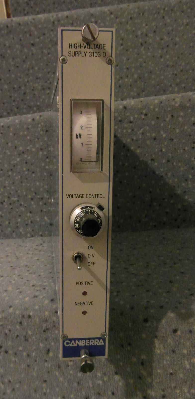 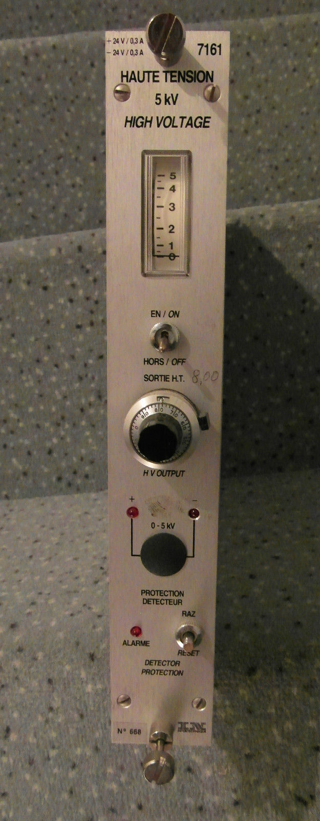 Image 37 and 38: HV
supplies for NIM
4. Shaping amplifier The shaping amplifier follows the charge sensitive preamplifier stage and performs three functions: a.
Providing an output pulse having a much faster return to the baseline
than the charge sensitive preamplifier output pulse. This is especially
important at high count rates, where pulses from consecutive events can
‘pile up’.
b. Filtering noise from the preamplifier output signal. c. Providing extra gain to the signal, which may be very small (sub mV) at the preamplifier output. For the shaping amplifier a Canberra 2022 ampifier will be used, which provides Unipolar shaping with one differentiator and two active filter integrators. The differentiator is placed early in the amplifier to insure good overload recovery. The integrators are placed late to minimize noise contribution from the gain stages. The amplifier offers six front panel selectable pulse shaping time constants: 0.5, 1, 2, 4, 8 and 12 μs. A baseline restorer is employed for optimum performance with high resolution detector systems. The gated baseline restorer automatically adjusts the restoration rate and threshold optimizing performance to the incoming count rate and system noise level. Simultaneous unipolar and bipolar outputs are available at both front and rear panel BNC connectors. The bipolar output can be used for counting, timing, or gating. See reference 22, reference 23 and Image 39 for the Canberra 2022 ampifier NIM module.  Image 39: Canberra
2022 frontside
The Canberra 2022 amplifier offers at the backside a power supply connector for connecting the pre-amplifier with a 9-pin D-sub connector. The layout of the pins is as follows:
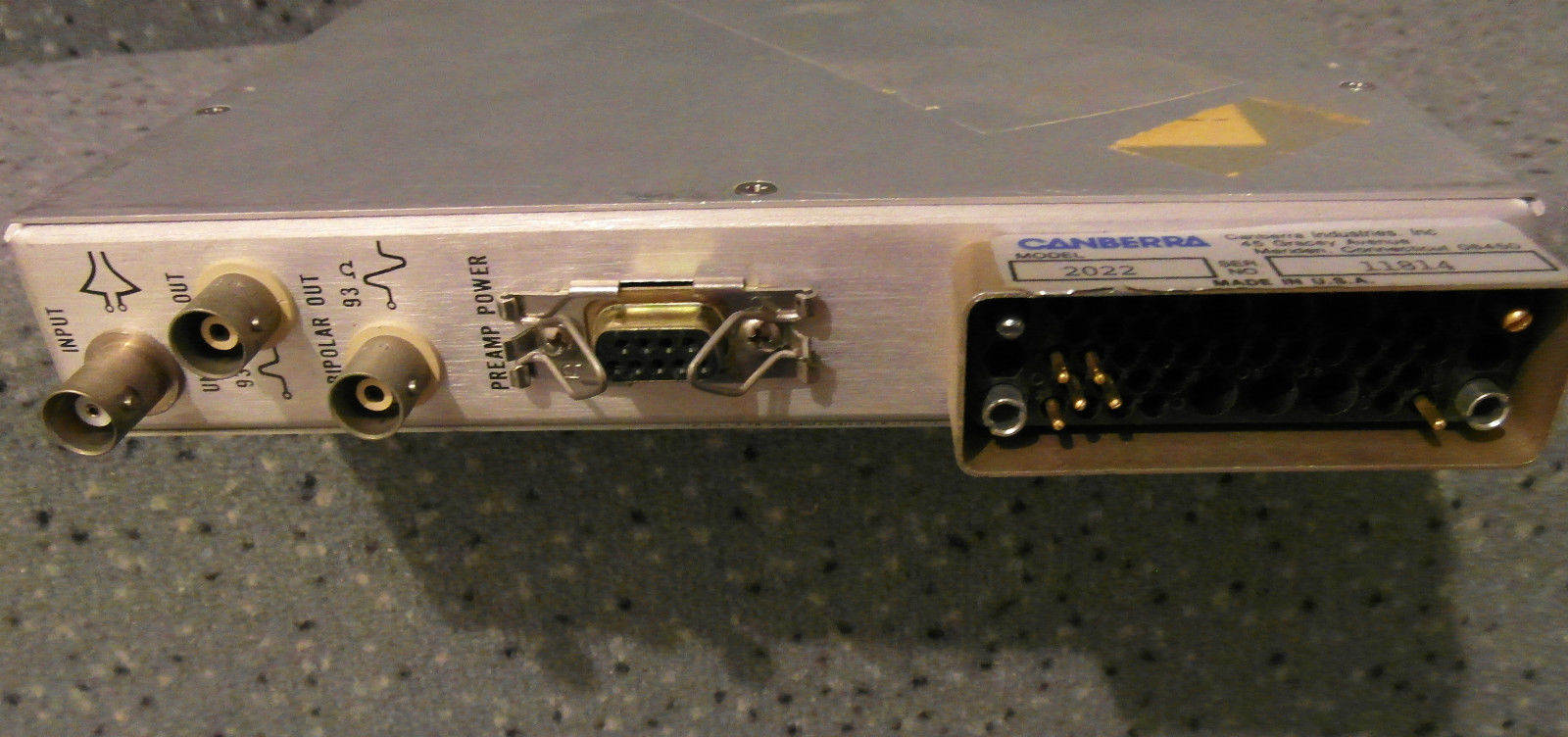 Image 40: Canberra
2022 backside
Two more amplifiers are present: the Ortec 452 Spectroscopy Amplifier, a linear shaping amplifier (image 41a) and the Silena Model 7613 (image 41b):   Image 41a and 41b: Ortec 452 Spectroscopy Amplifier and Silena 7613 Amplifier (© FRS 2016) 5. Single channel analyzer The single channel (pulse height) analyzer (SCA) is an electronic signal processor (a fast timing discriminator) with the function to find a maximum of a pulse by finding the zero of its slope. Analog input pulses that cross the discriminator threshold are converted to standard logic pulses at the output of the timing discriminator. These logic pulses can be counted in a counter/timer or scaler. The counting noise pulses are filterred out by setting the discriminator threshold just above the noise level. See Image 42 for the Tennelec TC 441SCA NIM module. 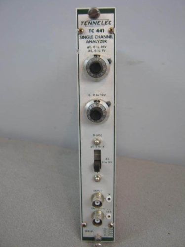 Image 42: Tennelec TC
441 single channel analyzer for NIM
6 Pulse counter Over a specified time interval the pulse counter counts incoming positive pulses from the SCA that have crossed the discriminator threshold and displays them in a display. When the counter lacks a timing option a separate timer module needs to be installed. See Image 43 for an example of the corrsponding NIM module.  Image 43: Example of
a counter for NIM
7. Ratemeter The ratemeter is not strictly necessary when a counter is present. Equally, when a counter is not present a ratemeter can be used. The ratemeter measures the counting rate of randomly arriving pulses or the frequency of periodic signals over a specified time interval. Depending on the age of the NIM ratemeter the display can be rather primitive up to current standards. Nevertheless they usually do their job without problems. See Image 44 for my Canberra 2081 rate meter NIM module, image 45 for my Berthold LB2232 ratemeter and image 46 for an example of an early rate meter with digit indicators . The Canberra Model 2081 Linear Ratemeter (reference 24) is an extremely stable averaging ratemeter which accepts positive or negative input signals (selected internally) at its front or rear panel connectors, scales them for the selected Range, averages the counts and displays the averaged count on an easy-to-read front panel linear meter. The Range switch offers seven full scale ranges, from 10 to 10 million counts per second, plus an eighth range (1/4 scale) of 25 million counts per second. If the input count rate exceeds the selected Range by 28%, the meter will indicate full scale for up to five seconds, then the unit will begin averaging the input signal again. The averaging time is 10 seconds on the 10 count/second range and 1 second on the other ranges. Zero suppression of 25% of range is provided by a 22-turn screwdriver-adjusted control on the front panel. The Model 2081 has a rear panel (0 to +5 V) recorder output with better than ±0.3% nonlinearity. The 7 cm (2.75 in.) front panel antiparallax meter has less than 2% nonlinearity. The Berthold LB 2232 ratemeter has an adjustable time range from 0.1 to 100 sec, an adjustable counting range from 2 to 100,000 counts per second, an adjustable background suppressor and a recorder output, adjustable from 0 to 10 V full scale. 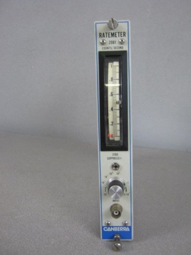 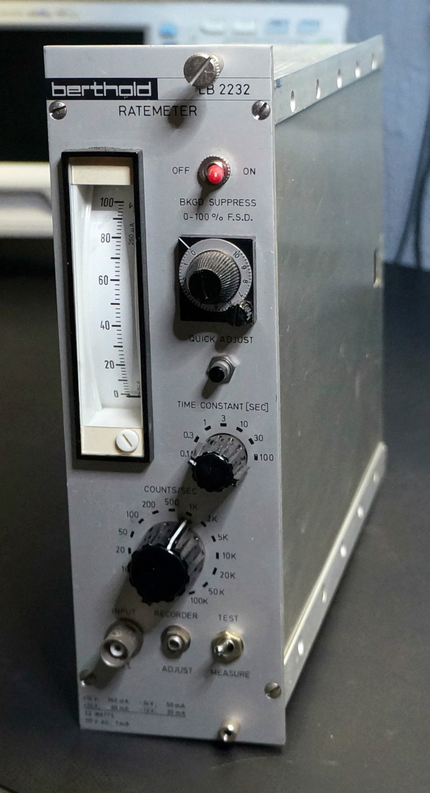 
Images 44, 45 and 46:
Examples of rate meters for NIM (left and centre analog
display, right digital display)
An alternative method for obtaining a counter is by constructing one with an Arduino. See reference 25 for details. It can be made in a defective NIM module (cheap on eBay!) or contained in a metal box. In the latter case a separate power supply will have to be added and in that case I should also add an LCD display, which is easy to connect to an Arduino and adds little cost. 8. Analog to Digital Converter An ADC can be useful when we want to convert our analog output into digital signals for processing in a computer. This is not strictly a requirement for the setup of our Fusor monitoring system. Our ADC is a Canberra Model 8076 (image 47), which is not the easiest ADC to deal with.  Image 47: Canberra ADC (©FRS 2016) The reason for the problems in dealing with a Canberra 8076 ADC is because of the programmable character of the device. This requires a lot of hard work, or acquiring the relevant software for it. Apparently a better choice is the Canberra Model 8075 ADC, which has analog settings. Data Processing pc-card For processing digital ADC signals in a computer we make use of a Nuclear Data pc-card (image 48):  Image 48: Nuclear Data pc-card (© FRS 2016) No further infomation is currently available for this card.  Additional NIM-modules Ortec 579 Fast Filter Amplifier The ORTEC Model 579 wideband Fast-Filter Amplifier (image 49) with gated baseline restorer enhances fast-timing measurements by improving the noise-to-slope ratio and providing ultra-high count rate spectroscopy capability. It has the following features: • For fast timing with germanium and other semiconductor detectors • Fast <8-ns rise time • Independent integration and differentiation • Gated baseline restorer • Pole-zero cancellation • 50-Ω delay cable clipping • Voltage gain X0.9 to X500 • Output drives to ±5 V on a 50-Ω load  Image 49: Ortec 579 Fast Filter Amplifier (© FRS 2016) MPI Dual Gate Pulse Generator This module (image 50) provides very precise delays for exact pulse triggering, syncing, delaying and gating events from two input gates. This generator ais used in many types of experiments, controls and processes where electronic timing of a single event or multiple events to a common timing reference is needed. This particular module can generate two independent pulses at certain independently chosen time points for two individual gates in a chosen order (" early" and " late") in order to trigger or synchronise other (measurement) modules or devices. As an example: It could be used to charge pump mosfet devices and at the same time triger a device to (delayed or advanced) collect a signal originating from the charge pumped device. The pulse time delay ranges from 100 ns to 10 sec. The module has Lemo-type connectors. Further characteristics of this particular brand of module are not available. We appreciate your feedback when you should have any documentation!  Image 50: MPI Dual Gate Pulse Generator (©FRS 2016) MPI Dual Gate Pulse Generator Oscillator This module (image 51) is more or less similar to the previous module, though it can provide a pulse (delay) for one channel only. The pulse time delay ranges from 1 µs to 1 min. The module has Lemo-type connectors. Further characteristics of this particular brand of module are not available. We appreciate your feedback when you should have any documentation! Note: The manufacturer of the MPI brand modules is unknown to find for us when searched on the internet. However, the module in image 51 has English text on it, except for the word " Oszillator", which is definitely German. This might indicate a German origin of these modules, possibly relating to the "Max Planck Institut für Kernphysik" (MPI).  Image 51: MPI Gate Pulse Generator Oscillator (©FRS 2016) MPI Logic Fan In-Out This logic fan-in/fan-out module (image 52) has the basic function of combining inputs and distributing multiple outputs. Hence, they can be used for combining pulses, usually anode and dynode pulses from photomultipliers and combines the (logic) operations of TTL-to-NIM level translation. The module has Lemo-type connectors. Further characteristics of this particular brand of module are not available. We appreciate your feedback when you should have any documentation!  Image 52: MPI Logic Fan In-Out (©FRS 2016) LeCroy Model 428F The Lecroy Model 428F Linear Fan-in Fan-out module (image 53) has a similar function as the previous module. Manufacturer's description: "Each channel of the Model 428F Quad Linear Fan-In/Fan-Out contains 4 direct-coupled linear outputs. The bipolar inputs, together with the polarity switch, allow convenient summing of either anode or dynode pulses. An output swing of +100 mV to -2 V is compatible with all normal analog inputs (e.g., discriminators, ADCs, etc.) and also accommodates standard logic levels. Each of the 428F's inputs is provided with input protection circuitry which gives immunity to transient signals up to ±5 A for 0.5 microseconds. The incorporation of the polarity switch is particularly significant in that it enables convenient, direct use of the fanned-out dynode signals for multiple fast logic decisions, while the anode signal can be directly applied to a current-integrating ADC. All outputs are reverse-terminated and mutually isolated. The 428F utilizes a direct-coupled feedback-stabilized circuit design that provides excellent linearity, long-term stability, and uniformity of gain and pulse shape. The speed of the unit is suitable for all common photomultiplier and logic signals, and there are no duty cycle limita tions or rate effects in the Normal Mode. In the Inverting Mode, the 428F operates as a capacitively-coupled unit with a 400 µsec time constant, recovering to the average non-inverted DC input level. In addition, the 428F exhibits duty-factor related base-line shifts equal to twice that of a normal AC-coupled circuit. Thus, although the Inverting Mode provides great versatility and convenience in application, some care must be exercised when using this mode with wide inputs or at high rates. Specifications: Number of Sections: 4 independent sections with 4 inputs per section. A front-panel switch on each section which selects normal or inverting mode. INPUT No. of Inputs: 4 per channel; 50 ohm ±5 %; direct-coupled in non-inverting mode. In inverting mode operates as a capacitively-coupled unit with a 400 µsec time constant. Inputs protected against 0.5 µsec transient overloads, up to ±5 A. Signal Level Requirements: Positive or Negative analog signals. Reflection Coefficient: Less than 7% for inputs of 2 nsec rise time. OUTPUT No. of Outputs: 4 per channel; reverse-terminated; direct-coupled; for optimum output shape, three outputs must be terminated into 50 ohm. For proper operation, at least 2 outputs must be terminated on each channel used. Output Levels: Linear range in normal mode is limited to: +100 mV to > -2 V, with maximum amplitude of > -2 V into 50 ohm and gain of 1.0 ±2% up to -2 V. Linear range in inverting mode: +100 mV to > -1.5 V, with maximum amplitude of > -1.5 V into 50 ohm and gain of approximately 0.98 up to -1.5 V. Rise Times: 2.5 nsec, 10% to 90%, with outputs terminated in 50 ohm. Fall Times: 4 nsec 10% to 90%, with outputs terminated in 50 ohm. Integral non-linearity: ±1% up to -1 V. MISCELLANEOUS DC Offset: Adjustable with front-panel potentiometer. Care should be taken to readjust DC level whenever the Normal/Inverting switch is used. Stability: < 60 µV/°C in normal and inverting modes. Output DC Level Voltage Coefficient: < 25 µV/1% variation of any supply voltage in normal and inverting modes. Interchannel Isolation: 40 dB. Noise: < 750 µV R.M.S. Overload Recovery: Approximately 2 nsec with four simultaneous NIM level (-800 mV) inputs. GENERAL Rate: DC to 100 MHz typically. Input/Output: < 6 nsec. Duty Cycle Limitations: None for direct-coupled outputs. Packaging: RF-shielded AEC/NIM #1 module. Lemo-type connectors. Power Requirements: 80 mA at +24 V, 80 mA at -24 V, 160 mA at +12 V, 160 mA at -12 V. "  Image 53: LeCroy Model 428F Fan-in Fan-out (©FRS 2016) LeCroy Model 621 CL Quad Discriminator No data could be found for the 621 CL model (image 54), though for the 621 AL model the manufacturer states: "NIM Model 621AL Quad Discriminator LRS Model 621AL retains the format and operating features of particle physics' most widely used discriminator, the LRS Model 321 BL. A new hybrid input stage provides substantial improvement in input characteristics: an almost perfect impedance match to eliminate reflections and consequent multiple-pulsing; a drift-free -30 mV threshold; overload protection to withstand outputs from even the most serious phototube malfunc- tions; virtually no input dc offset; and a new standard of compactness and reliability. A threshold monitor test point is provided on each channel to permit accurate and repro- ducible threshold settings using an external DC voltmeter. Output durations are adjustable from 5 ns to 1 us and are highly stable and independent of input amplitude, duration, and rate. Their long-term stability is excellent, permitting their direct use in critical coincidence applications without any need for external clipping cables. Each channel provides five standard amplitude negative NIM current source outputs and one complementary output. The flexibility resulting from this doubling of the output fan-out capability over previous circuits permits simpler and more efficient logic design. This greatly increased fan-out is achieved by means of a new output circuit design that utilizes very little quiescent power. The -30 mV threshold offered by the Model 621AL is almost a factor of two lower than that of the most sensitive previous circuits. It will permit experimenters to routinely reverse-terminate photomultiplier anodes. This procedure, coupled with the greatly im- proved input termination characteristics of the 621AL, greatly reduces the possibility of multiple-pulsing due to input reflections in the system. The pulse-forming circuit in the Model 621AL is deadtimeless (updating), and the unit may be retriggered during the time an output from a previous input signal is being produced. NIM Model 621AL QUAD DISCRIMINATOR INPUT CHARACTERISTICS Signal Input: Threshold, -30 mV to -1.0 volt (continuously variable up to -600 mV); front-panel screwdriver adjustment (screwdriver included); 50 Ohm protected to +/-5A for 0.5 us, clamping at +1 and -7 volts; reflections <2% for input pulses of 2 ns risetime; stability <0.2%/'C over 200 C to 600 C operating range; offset 0 -1 MV; threshold monitor has 1 0: 1 ratio of monitor voltage to actual voltage. Gate: Slow gate via rear connector and rear panel ON-OFF switch; rise and fall times, approximately 50 ns; clamp to ground from +5 inhibits; direct-coupled. OUTPUT CHARACTERISTICS Bridged Negative Outputs: 2 pair; NIM; quiescently 0 mA, -32 mA during output; duration, 5 ns to 1 us, continuously variable up to 600 ns via front-panel screwdriver control (narrower widths possible at slight expense of amplitude); risetimes and falltimes typically 2.0 ns (max. 2.5 ns), 1 0% to 90%. Output falltimes slightly longer on wide output durations. Width stability better than +/-0.2%/' C maximum. Fast Negative Timing Output: One; NIM; quiescently 0 mA, -1 6 mA during output. Other characteristics same as above, except risetimes and falltimes are typically -- 1.3 ns (max. 1.6 ns), and minimum width is -- 6 ns. Complementary Output: One; quies cently - 1 6 mA, 0 mA during output. Other characteristics same as for Fast Negative Timing Output. GENERAL Maximum Rate: 110 MHz typical, input and output. Double Pulse Resolution: Less than 9 ns. Time Slewing: 1 ns for input amplitudes 1 1 0% of threshold and above. Input-Output Delay: 9.5 ns typical. Multiple Pulsing: None; one and only one output pulse of preset duration is produced for each input pulse, regardless of input pulse amplitude or duration. Packaging: In RF shielded AEC/NIM #1 module; Lemo-type connectors. Current Requirements: -6 V at 430 mA; +6 V at 150 mA; -12 V at 165 mA; +12 V at20 mA; -24 V at 85 mA."  Image 54: LeCroy 621 CL Quad Discriminator (©FRS 2016) LeCroy Model 365AL 4-Fold Logic Unit According to the manufacturer, the LeCroy Model 365AL 4-fold Logic Unit (image 55) has the following functions: "LeCroy's NIM logic units offer flexibility, versatility, high speed and performance packaged in a single width NIM module. All together they provide the functions of majority logic, up to 4-fold coincidence, fan-in and fan-out and AND/OR Logic along with > 110 MHz operation. Each of the channels accept up to 2, Model 622, or 4, Model 365AL and Model 465, standard NIM logic signals. Both the 365AL and the 465 have inputs which may be individually enabled or disabled without altering cabling or termination by means of front-panel switches. In the 465, with all inputs enabled, four inputs are required. Disabling the logic inputs is equivalent to reducing the number of simultaneous negative input signals required for an output. Thus, each channel may be programmed for 4-fold, 3-fold or 2-fold logic decisions. With only one input enabled, each channel operates as a logic fan-out. The 365AL, however, has a selectable number of coincidence values to allow programming of one to four simultaneous input signals required for an output. Thus, it can operate similar to the 465 or can be used for the majority logic as well as a logic fan-in. Alternatively, the 622 features 4 channels with switch selectable AND or an OR output condition of the two inputs. All three units offer at least 2 sets of bridged outputs and at least one complementary output as well as continuously adjustable output pulse duration. The output pulse width is set via a front-panel screwdriver control pot from 5 nsec to 600 nsec for the 622. The outputs are highly stable and independent of input amplitude, duration and rate. All units are updating and can be retriggered before the end of an output pulse. The 465 also has bridged overlap outputs (-32 mA) whose output pulse width is equal in duration to the coincidence overlap. Specifications: Model 365AL INPUT Logic Inputs: 4 Lemo-type connectors; 50 ohm impedance; negative NIM level input requirements; each input can be separately enabled or disabled. Veto Input: Lemo-type connector; 50 ohm impedance; negative NIM level input requirements. Requires 3 nsec minimum width delayed 3 nsec from leading edge of input. Bin Gate: Via rear connector; clamp to ground from +4 V inhibit; rise times and fall times < 50 nsec. OUTPUT Outputs: 3 pairs; 2 negative (quiescently 0 mA, -32 mA during output), one complementary (quiescently -32 mA, 0 mA during output). Fan-out: 6-fold, if each output drives two 50 W loads. (Any used output pair should drive 25 ohm for proper amplitude and shape.) Duration: Continuously adjustable from less than 4 nsec to greater than 50 nsec by means of front-panel screwdriver-adjustable potentiometer. Updating. Output Rise and Fall Times: 1.2 nsec typical. Fall time is 2.2 nsec maximum at 10 nsec pulse width and longer. GENERAL Functions: AND; OR; Majority Logic; Leading Edge Inhibit; Complement; Pulse standardization without multiple pulsing; coincidence level determined by front-panel selector. Coincidence Width: 1 nsec and up, determined by input pulse durations. Rate: 150 MHz minimum. Input-Output Delay: Approximately 10 nsec. Double Pulse Resolution: Typical 5 nsec; (6.5 nsec for triple pulses). Packaging: NIM single-width module; Lemo-type connectors used for all inputs and outputs. Power Requirements: 55 mA at +12 V (increases to 120 mA if both channels in 4-fold coincidence), 165 mA at -12 V, 22 mA at -24 V."  Image 55: LeCroy 365AL 4-Fold Logic Unit (©FRS 2016)  Neutron Scintillation Detector with PMT Despite the fact that a Helium-3 gas proportional neutron detector is by far the best option for detecting and counting neutrons, it was possible to acquire a quite rare LiI(Eu) scintillation detector. It came form a SAIC neutron detector and it is rather small with a diameter of 12 mm. It is epoxy sealed onto a plastic light guide, contained in an aluminium cylinder, closed at one end, with an outer diameter of 18 mm and a wall thickness of 1 mm. The height of the cylinder is 12 mm (image 56): 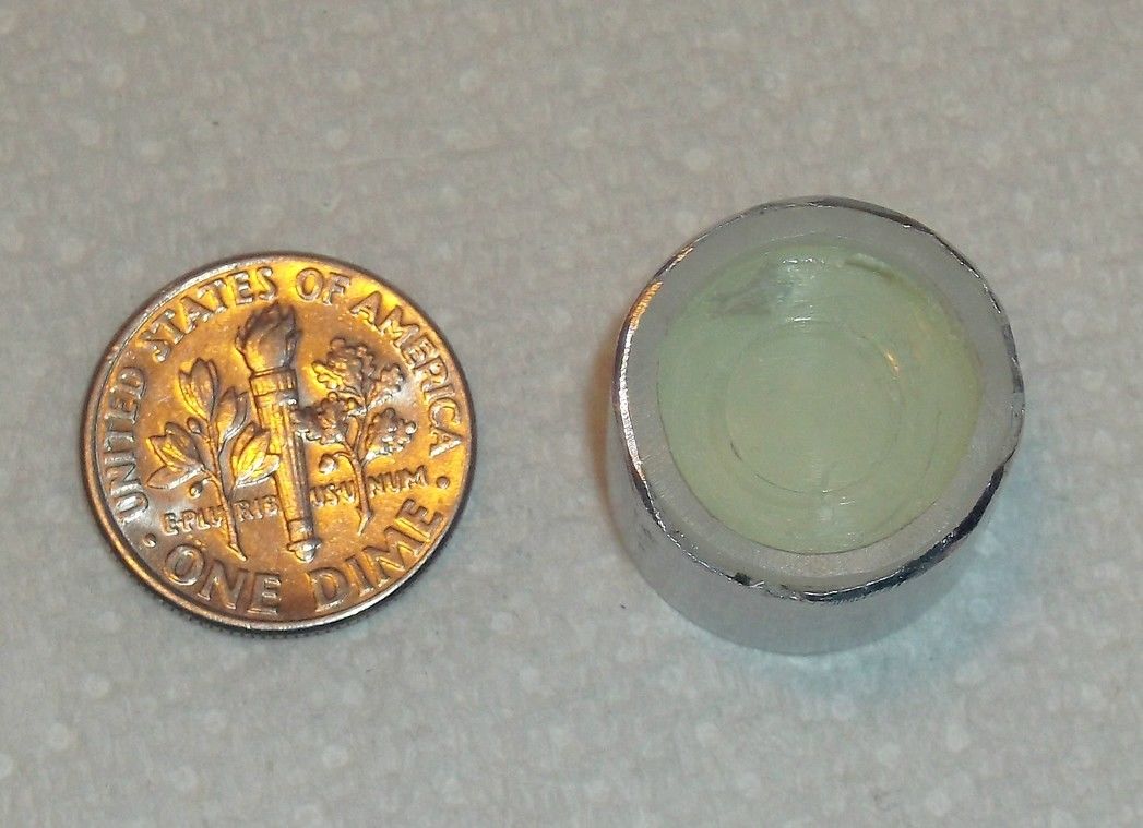 Image 56:
LiI(Eu) scintillation detector (top view)
As mentioned above the LiI(Eu) scintillation detector at the appropriate gain setting is capable of detecting neutrons (even fast neutrons, though at a lower absorption cross section) without interference of gamma's. Of course it requires to be placed onto a photomultiplier (PMT) and connecting to the PMT specific electronic circuitry, but it seemed worthwhile to add a second neutron detector to the rather difficult to operate SNM-32 Helium-3 corona detector. The general idea behind the setup of a double neutron detector system is to obtain a better interpretable outcome of possible D-D fusions. As mentioned, a LiI(Eu) crystal has a lower absorption cross section for capturing fast neutrons than for thermal neutrons, which is in the latter case approximately 940 barn (reference 26). It is therefore necessary to use a moderator for slowing down fast neutrons to thermal neutrons in order to obtain an optimal detection rate. The moderator consists of a material with a low atomic number, such as paraffin wax, polyethylene or similar hydrogenous material. If a neutron arrives in the moderator, it will be slowed down mainly by elastic scattering on the protons of the hydrogenous material but also by inelastic scattering off of hydrogen. Scattering back and forth through the hydrogenous material will continue until the neutron arrives at the same average energy of the surrounding atoms and hence has become thermal. By varying the thickness of moderating material, the detector sensitivity chamges as a function of neutron energy. Not every neutron, however, will be captured by 6Li for the following reasons:
The photomultiplier (PMT) of the reference article is wrapped in a mu-metal shielding and is then mounted in a 0.5 mm thick aluminium housing with 22.5 mm radius and 145 mm length. For our smaller LiI(Eu) crystal with half the radius (6mm) and a matching PMT with a radius of 7.5 mm, we will need to adapt the dimensions of the housing and moderator. Because the LiI(Eu) crystal is transparant to the emitted photonspectrum with a refractive index of n = 1.955, the coupling optical contact between the crystal and the PMT must be made by applying a coupling grease with a refractive index as near as possible. Details about setting up the PMT power supply and signal processing can be found in reference 27 referring to the Hamamatsu photomultiplier basics and applications, a valuable source of information. For the LiI(Eu) scintillator crystal a new, tiny Hamamatsu photomultiplier (image 57) was acquired with a slightly larger photocathode diameter than the crystal, together with a set of resistors and capacitors which are needed to make the voltage divider for the dynodes (image 58): 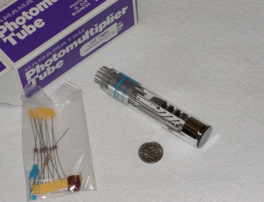 Image 57: Hamamatsu
PMT
 Image 58: Hamamatsu PMT
The PMT of images 57 and 58 has the Hamamatsu product number 6813341 and it has ten dynode stages for a gain of 105 to 106, a 12 pin base for socket F678-12D, a length of 95.3 mm (3.75 inch) and a photocathode diameter of 15mm (0.75 inch); it has a borosilicate window with a refractive index of 1.51 to 1.54. This PMT is of the bialkali type, i.e. with a maximal spectral response between 300 to 650 nm, peaking at 450 mm. The LiI(Eu) crystal has an emission peak at 470 nm, which means that both the crystal and the PMT match sufficiently. The PMT operates at a voltage between 850 to 1250 V, but performs best at 1100V. The PMT is believed to have the same pin-out as the Hamamatsu R1450 PMT (reference 28 and image 59).  Image 59: Hamamatsu
R1450 pin layout (© Hamamatsu Photonics K.K.)
The resistor divider network is connected to the Hamamatsu R1450 as follows (image 60):  Image 60: Hamamatsu R1450
resistor divider circuit (© Hamamatsu Photonics
K.K.)
The set of resistors and capacitors as supplied with the 6813341 PMT contained:
Table 8: Components
supplied with PMT
Making the PMT functional can of course be done with the HV power supply from the NIM-bin, followed by the amplifier and ratemeter. However, first of all the PMT with the attached LiI(Eu) crystal needs to be connected to the voltage divider as described e.g. in reference 29 and image 58 and 59. Reference 29 also mentions the possibility to use a PC's sound card (with free downloadable software, mainly for Windows XP or 7) as a multichannel analyzer. A different option for powering the PMT is with a Hamamatsu C2456 power supply (image 61 and 62):  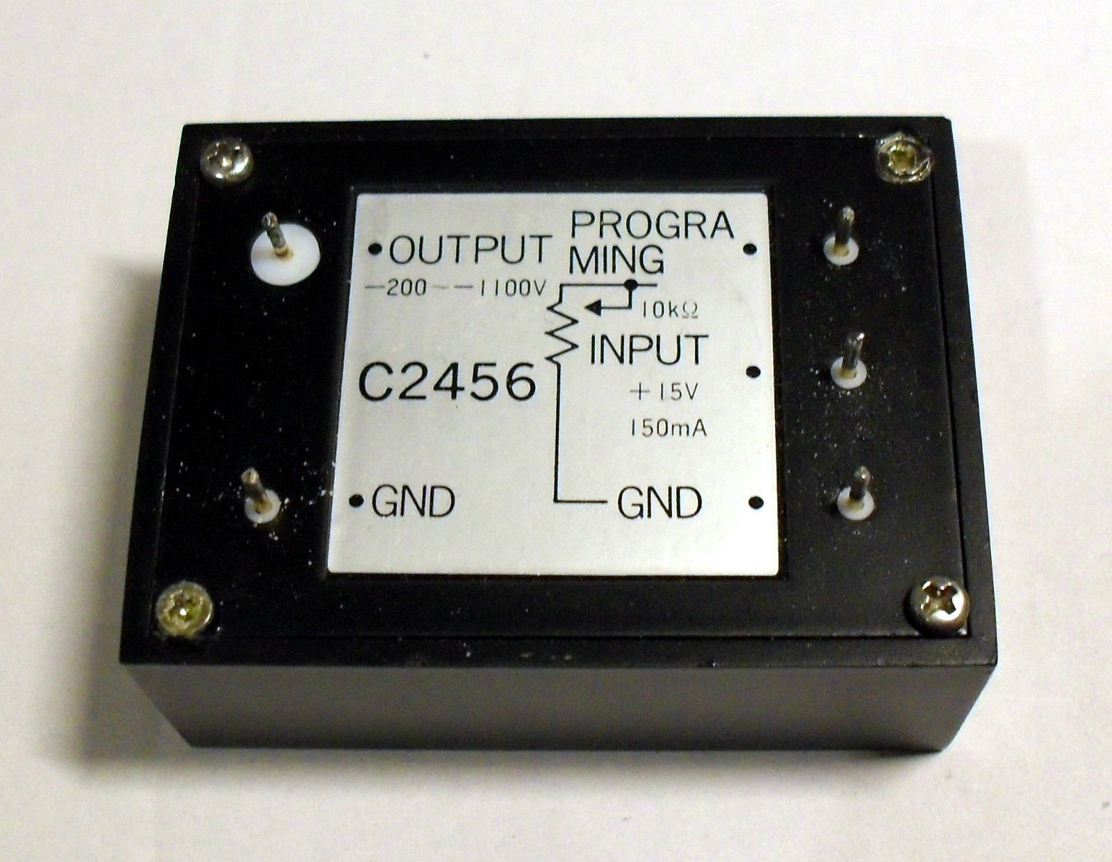 Image 61 and 62: Hamamatsu
C2456 power supply; front and backside (© ea4eoz, Spain)
The modular Hamamatsu C2456 power supply operates on 15V DC, 150 mA and needs a 10 kΩ potmeter for adjusting the voltage range from -200 up to -1100V. The datasheet provides more detailed information: reference 30. The Hamamatsu C2456 PSU is a rather small unit: the dimensions are l x w x h = 57.6 x 42.6 x 21.0 mm (2.27" x 1.69" x 0.83") and the lead pitch follows the standard 2.54 mm (0.1") spacing pattern. Therefore it fits onto a standard Veroboard PCB (stripboard) and can be combined with a printed circuit board power supply, e.g. a modular Bicker Elektronik BEN-0515 PSU (image 63), which connects to 85 to 264V AC and delivers 15V DC at 330 mA.  Image 63: Modular PCB power
supply 230VAC/15VDC (© supplier Germany)
The dimensions of the Bicker PSU are l x w x h = 48.5 x 36.0 x 20.5 mm (1.91" x 1.42" x 0.81"). Because no modular PCB power supply was present in our toolbox, a 15 V, 1000 mW PCB transformer with a 7815 voltage regulator, a 470 µF capacitor and four 1N4007 diodes were used to build a simple, regulated DC power supply (image 64):  Image 64: circuit for 15 V
DC power supply (© FRS 2015)
Image 65 shows the remaining component that we need for constructing the PMT high voltage power supply (HVPS), a 10 k wirewound 10 turns linear potentiometer with counting dial:  Image 65: Wirewound ten
turns potentiometer (© supplier GB)
For ease of operation the high voltage PMT power supply can be upgraded with a voltmeter in combination with a voltage divider. This will give an indication of the voltage at the output of the HVPS and it enables easy adjusting to the required output. For the voltmeter a four digit voltmeter was chosen (image 66). With a 1:100 ratio voltage divider, consisting of a 100 M and a 1 M resistor, a current will be drawn of 10.89 µA and an actual voltage of 1100 V will be displayed as 10.89 V, which reading will therefore need to be multiplied with 100. Please note that the 100 M resistor requires a 2 kV rating or else a series of lower rating resistors at a lower resistance can be used, e.g. 10 resistors of 10M in series, each covering a voltage drop of 100 V. The voltmeter requires a separate power line with an input of 4.5 to 30V DC and this means that it can be powered from the 15V DC power supply. 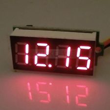 Image 66: Digital
voltmeter, 4 digits (© Supplier China)
The circuit for the complete HV power supply, however without the power supply lines for the voltmeter, is shown in image 67:  Image 67: HV power supply
circuit for PMT (© FRS 2015)
For coupling the crystal to the PMT an UV/VIS transparant immersion grease was used with a refractive index of 1.48, and a viscosity of 1.52 Pa at 25ŗC (image 68).  Image 68: Immersion
grease for coupling crystal and detector (Source: Supplier)
The refractive index of the immersion grease (1.48) matches closely the refractive index of the borosilicate window of the Hamamatsu PMT (1.51 - 1.53) but it is lower than the refractive index of the LiI(Eu) crystal (1.955), though not as low as the refractive index of a layer of air (1.00). Therefore adding immersion grease as an in-between layer is the best solution for coupling. The advantage of a coupling layer of immersion grease between the crystal and the PMT window is not only that a better light transmission is obtained but it provides also a filling to small scratches and pittings in both surfaces. A rather simple charge sensitive pre-amplifier for the PMT can be found in reference 31 but is also shown in image 69. 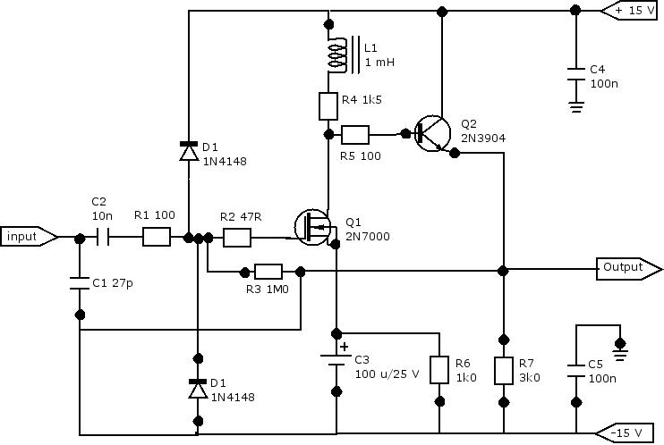 Image 69: Simple
pre-amplifier (courtesy: reference 25)
The pre-amplifier requires a power supply generating positive and negative 15V and it therefore may be a good idea to re-design the HVPS from image 55 into a circuit that generates both voltages. For that purpose we will need a different transformer and an adaptation of the circuit (image 70).  Image 70: Power supply for pre-amp and HV unit (© FRS 2015) The simple pre-amplifier can be made from the following list of components:
Table 9: Components for pre-amplifier Neutron Scintillation Detector with Photodiode By acquiring an Advanced Photonix amplified PIN photodiode, model PIN 10858 (image 71) it was possible to construct a neutron detector by applying ZnS(Ag)/6LiF wavelength shifting plastic fibers.  Image 71: Advanced Photonix Amplified PIN Photodiode (Source: Supplier) The PIN photodiode is extremely sensitive and has a built in high speed amplifier. The active area is 2x2 mm. The photodiode requires a power supply consisting of +9 to +15V DC and -9 to -15V DC, which can be supplied by a couple of 9V batteries. The four wires are coded Brown at Ground, Red at -15V, Orange at +15V and Yellow as signal output. The photodiode is sufficiently sensitive to detect a single photon when cooled and thoroughly shielded. Therefore we will need to fabricate a shielding (preferably cooled with a Peltier element) which is also capable of fixing the fibers to the window of the photodiode. The wavelength shifting plastic fibers need to be encapsulated in a light tight black sleeve prior to butting them to the window of the photodiode.  Gamma Monitoring Equipment When operating a Fusor a simple law rules: "Vacuum + High Voltage = Radiation". The type of radiation produced is Röntgen radiation with an energy related to the voltage applied, i.e. a Fusor operating at 30 kV will produce Röntgen radiation ("Bremsstrahlung") with an energy of maximally 30 keV from electrons of the grid (but higher from double-charged ions when present). Fortunately, an all metal reactor Fusor usually will keep Röntgen radiation inside the reactor, i.e. the radiation is shielded by the metal walls. A glass view port, however, will transmit Röntgen radiation to the outside of the reactor. Any concern about the amount of röntgen radiation produced by the Fusor can be dealt with by making an estimated calculation of the percentage of the röntgen radiation that will pass the vacuum chamber wall. Such a calculated estimation can be found on the theory page. Neutrons produced by the Fusor may induce gamma radiation by activation of elements in materials (n,γ reactions), e.g. iron, nickel, chromium etc. in stainless steel, etc. Because matter is relatively transparent to neutrons, except some elements with high capture cross sections like 10B, 6Li, 3He, 110Cd and 157Gd, there is no reason to worry about high levels of gamma radiation produced during operation of the Fusor. Nevertheless it is considered a good idea to have gamma radiation monitoring equipment observing the gamma output during operation of the Fusor. For our Fusor two different gamma monitors are used for directly monitoring gamma radiation, an Elscint Geiger counter and a Robotron dose rate counter (image 72). Monitoring of the accumulated gamma dose is done with a dosimeter (images 73 and 74).  Image 72: Elscint Geiger
Counter (l) and Robotron Dose Rate Meter (r) (© FRS 2015)
Elscint Survey Geiger Counter The Elscint is a simple Geiger counter of the survey type, model GSM-1. It has a measuring range from 0 - 5 mR/h and from 0 - > 2 R/h in four switching steps. Robotron Dose Rate Meter The Robotron dose rate meter, model KMSG 1/1M, is an instrument that can be set at a chosen level and that will give a continuous optical readout and an acoustical signal when the preset level will be exceeded. The instrument was acquired as new old stock in the early nineties from a military dumpstore after the collapse of the former German Democratic Republic in 1989. It was built by VEB Robotron- Messelektronik "Otto Schön" - Dresden and it left the factory "Werk 2 Pockau" in 9345 Pockau (Flöhatal) in March 1988. It is in my opinion a typical example of a cold war product, produced for the military. With its large numerical keyboard it looks like it has been designed as a mobile phone for the demented elderly population (though weighing 2.5 kg!) but the meaning is that it can be operated whilst wearing protective clothing and handshoes and this applies also to exchanging the batteryholder (big knob at the left side of the instrument). The instrument has for specifications:
The energy range of the dose rate meter indicates that it probably will not measure the dosis or dose rate from Röntgen radiation which is emitted at a lower level of maximally 30 keV. Please note that for measuring the actually absorbed gamma dose for a person it is essential to wear (and readout) a personal dosimeter. The advantage of a dosimeter is that it is based on an ionisation chamber and therefore also measures lower energy gamma radiation, such as Röntgen radiation but again not below an energy of 30 keV, as pen dosimeters usually have a measuring sensitivity range from 50 keV to 3 MeV.  Dosimeter A personal dosimeter is a fountain pen like instrument (image 73), in fact an ionisation chamber as detector with an electrometer as measuring instrument, which is loaded with a preset electrical charge that is partially removed for each event when gamma radiation hits the dosimeter.  Image 73: Two dosimeters
for different ranges (© Supplier)
Image 64 shows two dosimeters for different ranges, one with an orange coloured ring, the FH 39B, which measures from zero to 50 R full scale and one with a cyclamen coloured ring, the FH 39C, which measures from zero to 500 R full scale. Both ranges are far too high for our purposes and are better suitable for nuclear war conditions and therefore we make use of a third and a fourth model, which measure from zero to 5 R full scale (FH39E, red housing) and from zero to 2 MSv full scale (FH39US, gold housing, image 74). The FH39E and FH39US do not fit into the FH390 resetter (below) and therefore will require a separate resetter.  Image 74: Dosimeter for
0-200 mR range (© Supplier)
The dosimeter accumulates radiation received and can be read out after a chosen time for knowing the radiation dose received during that time. After readout the dosimeter is set to zero with a charge resetter (image 75), the FH 390, which also permits readout of the absorbed dose by means of illuminating the scale of the dosimeter with a built in lamp.  Image 75: Resetter for
dosimeter (© Supplier)
The absorbed dose can be read when the dosimeter is in the resetter but also in the open workspace when the dosimeter is directed towards a light field (image 78): 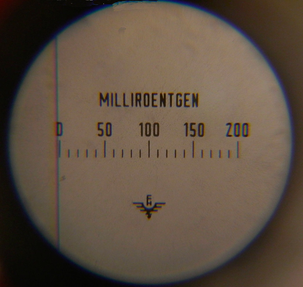 Image 78: View inside the
dosimeter (© Supplier)
Dosimeters based on the ionisation chamber/electrometer principle are not stable in their performance. With rising ambient temperature the readout rises also with maximally 0.3% per degree Centigrade. A dosimeter with a certain readout at 20°C will read max. 7.5% lower at minus 5°C and max. 6% higher at plus 40°C. Moreover, the charge of the dosimeter diminishes in time (self discharge), even when no radiation is absorbed, causing a drift of less than 1% of the scale length in 24 hours. This loss of charge is observed as an increase in absorbed dose. It is is therefore advised to wear the dosimeter not longer than five days before reading out and resetting to zero. To prevent this zero drift it is advised to store the dosimeter(s) fully charged. As mentioned before dosimeters are ionisation chambers with electrometers (image 79), which work with an electric charge, which is lowered when an ion pair is created by ionizing radiation and this proportional charge lowering is measured with the electrometer. With these particular dosimeters dating back from the 1960's the unit chosen here for measuring radiation is Röntgen (R), a rather old fashioned unit for radiation.  Image 79: Priciple of the Pendosimeter (© European Nuclear Society) Please note: This website uses "gamma radiation" as a general term for radiation emitted by electrons or from accelerated electrons (Bremsstrahlung), which is factually called Röntgen radiation, and for radiation emitted by the nucleus, particle decay or annihilation effects, which is factually called gamma radiation (reference 32). Ionizing radiation exposure is expressed as Coulomb per kg (C/kg), the amount of radiation required to create 1 Coulomb of charge of each polarity in 1 kg of matter and 1 Röntgen as unit equals 2.59 x 10⁻⁴ C/kg. The effect of gamma's is however more related to the absorbed dose, the amount of energy deposited, than to charge. The unit of the absorbed dose is the Gray (Gy) with as units Joule per kilogram (J/kg), the amount of radiation required to deposit 1 Joule of energy in 1 kilogram of matter. The charge to energy relationship is expressed by the formula Joule equals Volt multiplied by Coulomb or J = V x C. The biological effect of radiation on human tissue is expressed as Sievert (Sv), which for gamma rays is numerically equivalent to the Gray. Assuming that a dosimeter only is sensitive for gamma's than the relation from an ion dose in Röntgen measured by the dosimeter, via an energy dose in Gray, to an equivalent dose in Sievert is: 1 R ≈ 1 cGy ≈ 0.01 Gy
≈ 0.01 Sv ≈ 10 mSv
Therefore a dosimeter with a scale from 0 to 200 mR complies for the maximum reading with an equivalent dose of ≈ 2 mSv, the average annual dose for a non-radiological worker (a normal citizen). Similarly, the dosimeter with the 50 R scale measures maximally an equivalent dose of ≈ 0.5 Sv and the dosimeter with the 500 R scale measures maximally an equivalent dose of ≈ 5 Sv, a true LD50 dose (see next paragraph)! An acute full body equivalent single exposure dose of 1 Sv will cause slight blood changes, but a similar dose of 5 Sv is considered lethal for 50% of the exposed population. Natural exposure to gamma radiation is about 1 to 3.5 mSv per year, depending on the location on earth where a person lives. It should be clear that exposure to radiation should be avoided as much as possible. e.g. by running a fusor at not too high potentials and by keeping a distance form the fusor under operation as large as possible. X-ray Gamma Counter As mentioned before most standard gamma measuring equipment is not capable to measure X-ray radiation due to the relatively low energy emitted. Traditionally, ionization chambers were used for measuring X-ray radiation. In the last two decades scintillation plastics were developed, which, in a thin layer, by capturing low energy radiation emit photons. The scintillation plastic is coupled to a very sensitive photo diode for converting the photons into an electric signal. Image 78 shows a Hamatsu S8559 X-ray detector:  Image 78: Hamamatsu S8559 X-ray Detector (© Hamamatsu, Japan) The Hamamatsu S8559 detector consists of a S1337-1010BR Si-photodiode, which is coupled to a Cesium Iodide (Thallium doped) scintillation crystal. Cesium iodide has a relatively high stopping power due to its relatively high density and the high "Z" (atomic number). Cesium iodide is doped with Thallium as an activator to make it function as a scintillator material. The scintillation crystal has the following characteristics (reference 33):
The Si-photo diode S1337-1010BR has the following characteristics (reference 34):
 Image 79: Spectral Response of the S1337-1010BR Si-photodiode (© Hamamatsu, Japan) The spectral response of the S1337-1010BR Si-photodiode peaks at 960 nm (image 79), whereas the scintillation crystal has a peak emission at 560 nm. Therefore, the photodiode is not optimal efficient in detecting the scintillator photon emission. Enhancing the efficiency (e.g. by means of placing a wavelength shifter between crystal and photodiode) is not possible because the scintillation crystal is epoxy cemented to the photodiode. The Quantum Efficiency (QE) for a photodiode is the number of electron-hole pairs that can be detected as a photo current divided by the number of incident photons. It is expressed at a particular wavelength according to the following expression:  S(λ) = photosensitivity in A/W at specific wavelength λ = wavelength in nm The spectral sensitivity of the S1337-1010BR Si-photodiode at the peak wavelength of the CsI(Tl) crystal can now be calculated: In image 70 we observe at 560 nm a photosensitivity of approx. 0.36 A/W. The quantum efficiency QE(560) is (0.36/560).1240.100% = approx. 80% A suitable circuit for using the S8559 detector as a X-ray detector can be found in reference 35 and is shown in image 80:  Image 80: Schematic Circuit for X-ray Detector (FRS 2015) Radiation absorbed in the scintillater crystal emits UV or visible light which is detected by the photodiode coupled to the scintillator. The scintillator crystal is wrapped with reflective material (aluminium foil) to prevent background light from entering through the scintillator. At the same time the aluminium foil collects the generated light onto the photo diode. The crystal and detector need to be protected with a layer of beta shielding material to prevent detection of beta radiation. Another circuit for this detector was found in reference 36 and is shown in image 81: The setup of the circuit in image 81 is also based on a configuration with the photodiode in the photovoltaic mode. The advantages of such a configuration are:
The minimum current output from the photodiode will be in the range of a few hundred femto amps DC and requires a FET input opamp in inverting configuration as a current to voltage converter. For the opamp an AD515AL has been chosen because it has a guaranteed maximum bias current of 75 fA, which (theoretically) permits to measure currents > 75fA. The scale factor (or feedback) resistor was set at a value of 1 GΩ in order to prevent saturation of the opamp in the current to voltage converter. The photodiode S1337-1010BR has a maximum dark current of 200 pA (2E-10 A) and this will yield 2E-10 A x 1E9 Ω = 0.2 V output, which is an acceptable low value far below the point of saturating the opamp. The minimum photodiode current output of 200 fA yields in the opamp an output of 200E-15 x 1E9 = 2E-4 V, which needs to be amplified for further processing. For the voltage amplifier stage an AD524C precision instrumentation amplifier has been chosen. The ADC524C has fixed gains of 1, 10, 100 and 1000. In the circuit a gain has been chosen of 100 for enabling processing in a 12-bit ADC. The output is filtered to get rid of noise caused by the high amplification. All capacitors in the circuit should be chosen as ceramic capacitors. Gamma-Spectrometry After having gained some experience with photomultipliers it seamed logical to construct a gamma-spectrometer for identifying radinuclides by measuring the energies emitted. We have decided to use a separate page on this website for this purpose: Gamma-Spectrometry  Construction of a Neutron Calibration Source It is nice to have a couple of neutron measuring detectors but how can we be sure that they indicate the correct amount of neutrons measured? A solution is to calibrate the neutron measuring device against a calibrated neutron source. Commercial calibrated neutron sources are available on the market but are costly and may need a licence for having, handling and storing them. Theoretically, we could construct such a neutron source ourselves. The questions is: will it be of any use for our purposes? Let's do an experiment: The basis for our self-constructed neutron source is an ionisation smoke detector, which usually contains an α-emitter, such as Americium-241. Should one want to repeat our experiment than one should be in a hurry to obtain such an ionisation smoke detector because in most civilised countries they are forbidden for sale since about the year 2000. Nevertheless they can be found in many homes and sometimes they are offered on eBay by private sellers (forbidden now in the EU to be offered by commercial sellers). The amount of Am-241 in smoke detectors varies from 5 kBq to 40 kBq and it is obvious that we should obtain the strongest possible. In our home, hanging in the attick, I found an old 1980's E.I. Irish brand smoke detector, model 100B, which contains 0.9 µCi (33.3 kBq) Am-241, though a sticker inside erroneously mentioned that it contains 0.9 pCi. The Am-241 source inside the smoke detector emits alpha's according to  The emitted alpha's have an energy of 5.6 MeV or 5.6x10⁶ eV. For the ionisation of 1 molecule we need about 34 eV and therefore one alpha particle produces 5.6E6/34 = 1.6x10⁵ ions. Our smoke detector contains 0.9 µCi (33.3 kBq) of Am-241 and this amount of radioactivity is equivalent with 3.3x10⁴ desintegrations (= alpha's) per second. The total number of ions produced by such a tiny radioactive source is 1.6x105 x 3.3x104 = 5.3x10⁹ ions per second. The range of an alpha particle in air is about 4 centimeters, about a few millimeters in human skin and about 40 micrometers in Beryllium metal. The very low range of the alpha particles requires that we press the Beryllium against the Am-241 source in order to obtain the nucleair reaction:  Except measuring neutrons we will therefore also observe quite an amount of gamma's of 60 keV and 4.4 MeV energy (but most of all we will notice only the high energetic gamma's). This has to be taken into consideration for not affecting our potentially gamma sensitive neutron detector. The maximum cross section of the 9Be(α,n)12C reaction with 5.6 MeV neutrons is 542 mbarn and the yield of a commercial Am-241/Be-9 source is about 2.0 to 2.4x10⁶ neutrons/sec per Ci. For our 0.9 µCi smoke detector source this would be on average 2 neutrons/sec! In practice it will be less because our Am-241 is not with all sides fully embedded in the Beryllium matrix but partially fixed onto the carrier with only a single side pressed to the Beryllium metal foil. In fact, our Am-241 source will emit α-radiation as a 4π sphere and therefore at the best we will only catch a quarter of the emitted alpha's in our Beryllium, yielding with our smoke detector radioactive source maximally about 30 neutrons/min. That's a rather low amount of neutrons that we can expect and it certainly will cause problems to detect such a low amount of neutrons by our neutron detectors (too low signal/background ratio). For a sufficiently high signal/noise ratio we would need to sample an amount of several hundreds of smoke detectors in order to get a yield of about 1000 neutrons/sec, which is quite an impossible task and moreover with such a huge amount of smoke detector radioactive sources we also would have to isolate the Am-241 from the carrier plates and concentrate it prior to adding Beryllium metal. As a trained and qualified radiochemist it will be quite possible for me to isolate Am-241 from the carrier plates and to convert and concentrate it in a chemical state suitable for binding into a Beryllium matrix yielding a maximally efficient AmBe radiation source, but a rather comprehensive laboratory setup would be required to ensure my own safety. The average amateur lacks the knowledge, as well as the experience and the highly specific laboratory environment. Therefore this project is absoluty not advised, particularly in view of the severe risk to your health by disassembling hundreds of smoke detectors and chemically processing and concentrating the radioactive substance because Am-241 is highly poisonous and additionally Am-241 dust particles inhaled may induce (lung) cancer. Forget about it! Setup of Equipment Image 82 shows a preliminary setup of the current monitoring equipment: 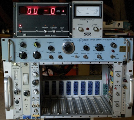 Image 82: Preliminary
setup of monitoring equipment
The preliminary setup shows the NIM-bin (bottom) with the following modules from left to right: HV power supply 5 kV, HV power supply 3 kV, shaping amplifier and at the far right a custom made module and the strip of standard power outlets from the NIM-bin. Middle position on top of the NIM-bin, the light blue coloured pulse generator, top position left (digital) triode vacuum gauge controller and top position right (analog) thermocouple vacuum gauge controller. The Spectroscopy Amplifier, the Single Channel Analyzer, the Ramp Generator and both the Ratemeters have not yet been placed into the NIM-bin.  |
|||||||||||||||||||||||||||||||||||||||||||||||||||||||||||||||||||||||||||||||||||||||||||||||||||||||||||||||||||||||||||||||||||||||||||||||||||||||||||||||||||||||||||||||||||||||||||||||||||||||||||||||||||||||||||||||||||||||||||||||||||||||||||||||||||||||||||||||||||||||||||||||||||||||||||||||||||||||||||||||||||||||||||||||||||||||||||||||||||||||||||||||||||||||||||||||||||||||||||||||||||||||||||||||||||||
 |
 |
 |
 |
 |
 |
 |
 |
 |
 |
 |
 |
Last Updated on: Sat Dec 31 15:30:07 2016 |